WARNING
The installation and configuration of Voldeno modules involves working with electrical equipment.
Improper installation can result in equipment damage, electrical hazards, and personal injury.
Overview
The Voldeno Bus is a distributed control network that interconnects all modules within a Voldeno smart home system. It provides power distribution (24V), ground connection, and a high-speed CAN-FD (Controller Area Network with Flexible Data-rate) communication bus with proprietary Voldeno messaging protocol for coordinated operation of lighting, climate, security, energy management, and other intelligent functions.
Key Characteristics
Protocol: CAN-FD bus with proprietary Voldeno message specification
Operating Voltage: 24V DC
Architecture: Linear daisy-chained topology (no loops)
Maximum Modules: 40 per single Voldeno Bus
Maximum Bus Length: 300 meters total
Termination: Dual 120 Ω resistors at bus ends (60 Ω effective bus impedance)
Maximum Stub Length: 1 meter
Bus Connector and Wiring Specification
Connector Design
Each Voldeno module features a single bus connector with four terminal pairs. Each terminal pair accommodates two wires, referenced below as Input (left position) and Output (right position). While electrically shorted (continuous connection internally), this Input / Output convention simplifies daisy-chaining topology and serves as a visual reference for installation discipline.
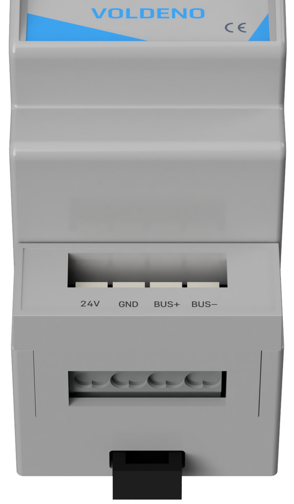
| Terminal Pair | Function | Input (Left) | Output (Right) |
|---|---|---|---|
| 24V | 24V Power Supply | 24V Input | 24V Output |
| GND | GND (Ground) | GND Input | GND Output |
| BUS+ | CAN High Signal | CAN High Input | CAN High Output |
| BUS- | CAN Low Signal | CAN Low Input | CAN Low Output |
Recommendation: Use appropriately rated wire gauge for both CAN signal wires (CAN+/CAN−) and the 24V power distribution.
0.5mm² (20 AWG) copper wire is recommended for easier connector push-in wiring and to minimize voltage drop.
The connector used for Voldeno Bus in DIN-mounted modules is WAGO 235-454/331-000.

The terminal parameters of this connector are as follows:
| cable connection technique | push |
| method of opening the clamp | button |
| single-wire cable | 0,2 … 0,75 mm² / 24 … 18 AWG |
| wire stripping length | 9 … 10 mm / 0.35 … 0.39 in |
Bus Topology and Constraints
Linear Daisy-Chain Architecture
The Voldeno Bus operates as a linear, non-branching topology:


Connection Method: Each module receives power and bus signals from the upstream module (Input terminals) and passes them to the downstream module (Output terminals), forming a linear chain.
Connector Orientation: Ensure consistent orientation during installation. Wire connections should never be reversed – power supply, so 24V / GND must not be applied to signal terminals, and vice versa.

Topology Rules
1. No Loops: The bus cannot form a closed loop. The start point (first module) and end point (final module) must never be directly connected to each other.
2. No Branching: All modules must be connected in a single linear sequence. Branches or spurs off the main bus line are not permitted.
3. No Unterminated Stubs: Any connection point that does not lead to a module must be properly terminated. All wiring branches and connections must be minimal length (see stub constraint below).
Distance and Module Constraints
Maximum Bus Length: 300 meters total measured along the entire communication bus from the first module to the last module. Power supply wires length is limited by the voltage drop and needs to be controlled by checking the voltage levels at module terminals (can be verified also from the Voldeno Studio).
Maximum Module Count: 40 modules on a single Voldeno Bus.
Maximum Stub Length: 1 meter maximum for any branch or intermediate connection that does not directly connect to a module. This constraint ensures signal integrity and minimizes reflections in the CAN-FD network.
Stub Definition: A stub is any wire or connection branch extending from the main bus line.
Examples include:
– Intermediate termination resistor leads
– Test point connections
– Bypassed module connections
– Power distribution branches not integral to the daisy-chain
Consequence of Violation: Exceeding stub length limits will result in signal reflections, CAN message corruption, bus communication failures, and potentially system-wide malfunction.
Bus Termination
Termination Overview
CAN-FD is a differential signal bus. Without proper termination, signal reflections occur at the bus ends, causing voltage overshoots, signal degradation, and communication errors. The Voldeno Bus requires dual 120 Ω termination (one at each end, resulting in 60 Ω total line impedance) to maintain signal integrity.
Bus termination is built-in in each DIN-mounted Voldeno module and is controlled with a physical switch, so no external termination resistors are required.
Termination Switch Location
Each DIN-mounted Voldeno module includes a built-in termination controlled by a physical switch. The location of this switch varies by module form factor:
4 DIN Module: Termination switch located at the bottom of the module enclosure.
2 DIN Module: Termination switch located at the right side of the module enclosure.

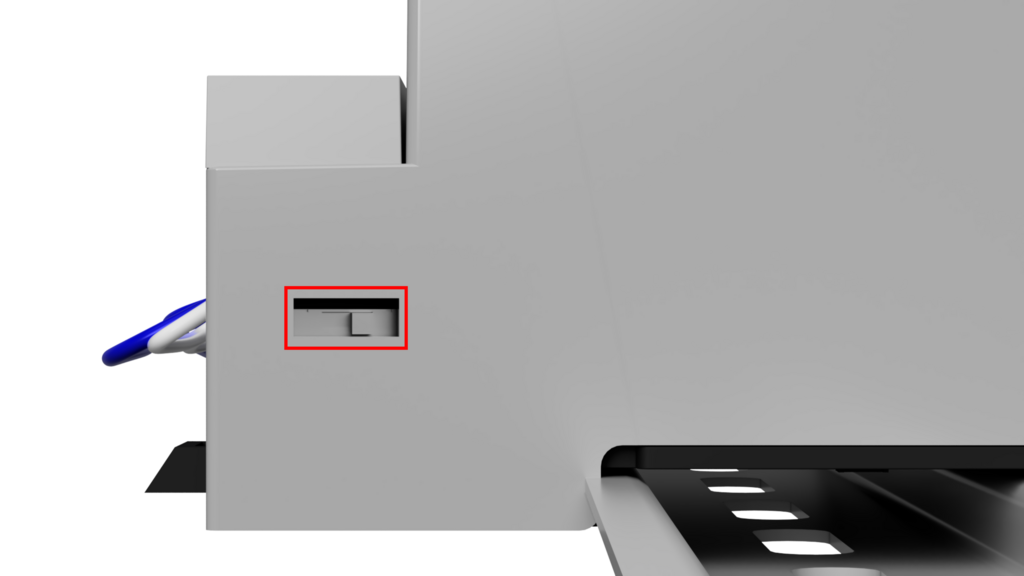
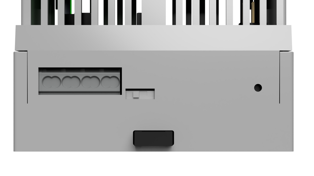
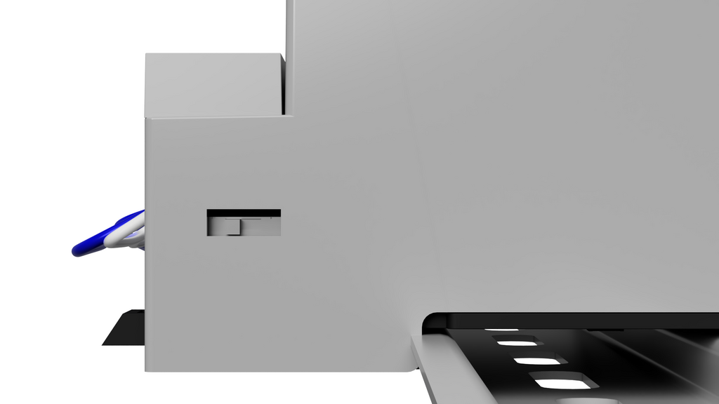
Termination Switch States
Left Position: Termination OFF (open circuit – resistor disconnected)
Right Position: Termination ON (resistor connected to CAN+ and CAN- bus lines)
Correct Termination Configuration
Requirement: The Voldeno Bus must be terminated at exactly two locations – one at each physical end of the bus:
1. The first module in the daisy-chain (physically nearest to the power supply)
2. The last module in the daisy-chain (physically farthest from the power supply)
Configuration Steps:
1. Identify the first and last modules in your linear daisy-chain sequence.
2. Set the termination switch to RIGHT position (ON) on the first module.
3. Set the termination switch to RIGHT position (ON) on the last module.
4. Set the termination switch to LEFT position (OFF) on all intermediate modules.
Termination Resistance: With both ends properly terminated (two 120 Ω resistors in parallel across the differential pair), the effective line impedance is 60 Ω, which matches the characteristic impedance of the CAN-FD transmission line and ensures optimal signal quality.
Consequence of Incorrect Termination:
– No termination (both switches OFF): Signal reflections, communication errors, and potential bus lockup.
– Single termination only: Asymmetric signal behavior, unreliable communication, intermittent module dropout.
– Intermediate module termination: Impedance mismatch, signal reflection at multiple points, bus failure.
Installation Steps
Step 1: Power Down
Ensure the 24V power supply to the Voldeno Bus is switched OFF and disconnected. Verify with a multimeter that no voltage is present on the bus connector terminals.
Step 2: Lay Out Module Sequence
Arrange all modules in the physical order they will occupy on the bus, from the power supply entry point to the farthest module. Ensure that the total wire run distance does not exceed 300 meters.
Step 3: Configure Termination Switches
Set all termination switches to the LEFT position (OFF) initially. You will adjust the first and last modules after confirming the full chain.
Step 4: Connect Power (24V/GND)
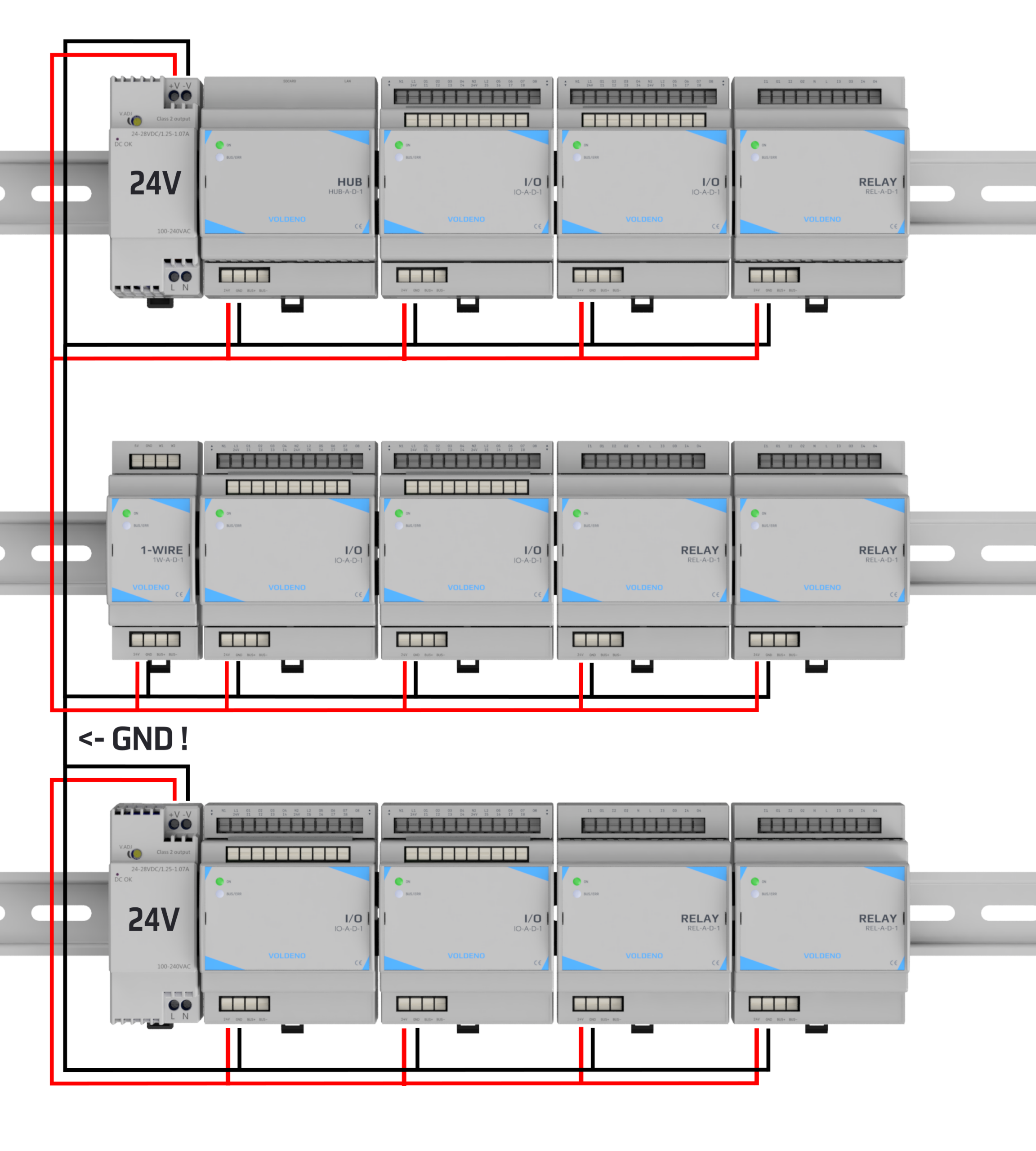
To minimize voltage drop and improve stability under load, do not distribute 24V/GND by daisy-chaining across the entire Voldeno Bus. Instead, feed each electrical cabinet row (or group of physically adjacent modules) from a dedicated 24 VDC power feed, then daisy-chain only within that row (or group).
Beginning at each cabinet row:
– Provide a dedicated 24 VDC feed (positive and GND return) from the power supply (or from a fused distribution block) to the first module of the row.
– Connect the 24V power positive to the Input (left) terminal of the 24V pair on the first module in that row.
– Connect the power supply negative output (GND return) to the Input (left) terminal of the GND pair on the first module in that row.
– Daisy-chain only within the same row: connect the 24V Output (right) terminal of Module N to the 24V Input (left) terminal of Module N+1 (for modules located in the same row).
– Daisy-chain only within the same row: connect the GND Output (right) terminal of Module N to the GND Input (left) terminal of Module N+1 (for modules located in the same row).
– At the last module in the row, leave the 24V and GND Output (right) terminals disconnected or capped/insulated.
Repeat bullets above for every additional cabinet row so that each row receives its own power feed, reducing the current carried along any single row chain and therefore reducing voltage drop.
In case the total power required by modules is larger than the power supply can provide, use multiple power supplies ensuring their grounds are connected.
Step 5: Connect CAN Bus Signals
Following a daisy-chain pattern:
1. Connect the CAN+ Input (left) terminal of Module 1 to the CAN+ signal source (typically from a gateway or primary controller).
2. Connect the CAN− Input (left) terminal of Module 1 to the CAN− signal return.
3. Proceed along the chain: connect the CAN+ and CAN− Output (right) terminals of Module N to the Input terminals of Module N+1.
4. At the final module, leave the CAN+ and CAN− Output terminals disconnected or capped with insulation.

Step 6: Configure Termination for First and Last Modules
1. Locate the termination switch on the first module in the chain (see top-left “TERM” mark on the image above).
2. Move the switch to the RIGHT position (ON).
3. Locate the termination switch on the last module in the chain (see bottom-right “TERM” mark on the image above).
4. Move the switch to the RIGHT position (ON).
5. Verify all intermediate modules have the switch in the LEFT position (OFF).
Step 7: Power On and Verify Communication
1. Power on the 24V supply.
2. Allow modules to boot (typically 2–5 seconds).
3. Using Voldeno Studio or the mobile application, verify that all modules appear in the connected devices list.
4. Test at least one control function (e.g., toggle a relay) to confirm bidirectional communication.
Step 8: Perform System Test
Perform a full system diagnostic through Voldeno Studio to verify all modules respond to commands, sensor readings are accurate, and no communication errors are reported.