Every AC output in the Voldeno I/O and RELAY modules switches at the voltage zero crossing. A dedicated ADC circuit tracks the mains sine wave and the module firmware computes the exact switching moment. Less arcing, smaller current surges, longer contact life.
# Zero-crossing switching: how the I/O and RELAY modules extend relay contact life

Every relay channel in the I/O and RELAY modules has its own tracking circuit on the switched line. A dedicated ADC monitors the shape of the mains sine wave, and the module firmware detects zero crossings and uses them to compute the exact moment the relay should operate. The result: for AC loads, the contacts close and open at a voltage near 0 V instead of at a random point of the sine wave. This is zero-crossing switching, known from industrial SSR relays, implemented in software on standard electromagnetic relays.
The feature is invisible on a product photo, yet it largely determines the service life of an output driving a heater or an LED lighting section: whether the relay runs reliably for years or ends up with welded contacts after a year or two.
# What destroys relay contacts
In building installations, mechanical wear is rarely what limits relay life. The dominant degradation mechanisms are two commutation phenomena.
The first is inrush current at turn-on. A cold heating element, an incandescent lamp, or an LED driver with capacitors at its input can draw a current many times the rated value during the first milliseconds. If the contacts close near the peak of the sine wave (325 V on a 230 V AC line), the full surge hits them at once.
The second is the electric arc at turn-off. Breaking a circuit at full voltage causes arcing between the separating contacts. Each arc melts a small amount of the contact surface. Over time the contact resistance rises, the contact heats up further, and eventually it welds shut or stops conducting.
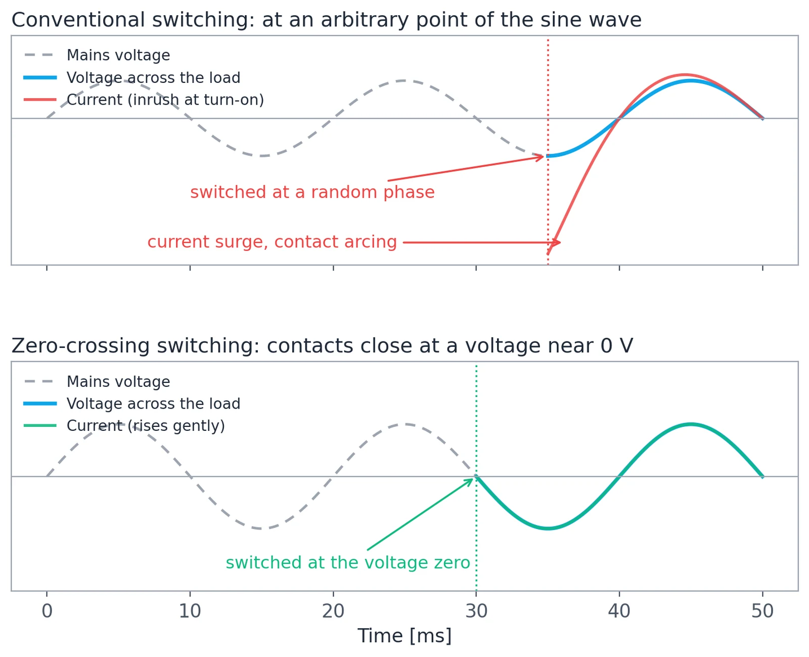
A conventional relay driven from a binary output knows nothing about the mains phase. The moment the contacts close relative to the sine wave is random, so statistically a share of all switching events always lands near the voltage peak.
# What zero-crossing switching is
Zero-crossing switching is a technique in which the relay contacts close or open exactly when the voltage sine wave passes through 0 V. The voltage across the load then rises gradually from zero instead of appearing at full value in a single step, and at turn-off there are no conditions for drawing an arc.
The benefits are well documented in industrial automation: contacts protected from inrush currents, no arc at disconnection, lower EMC emissions, and a clearly higher permissible load power for the physically identical relay.
This function is usually implemented as dedicated hardware: a special relay with a synchronization circuit, or a solid-state relay with zero-cross detection. At Voldeno we took a different route.
# How Voldeno implements it in software
In the I/O and RELAY modules, zero-crossing switching runs in software, on standard electromagnetic relays. Three elements make it work:
- Voltage tracking circuit. A dedicated measurement path with an ADC monitors the voltage waveform of the switched line and feeds its shape to the module's processor.
- Zero-crossing detection. The firmware detects every zero crossing in the sampled waveform and continuously measures the mains period.
- Prediction and lead time. When the installation logic requests a channel to switch on or off, the module computes when the next suitable zero crossing will occur and drives the relay coil early, by exactly the contact operate time. The contacts close right at the zero.
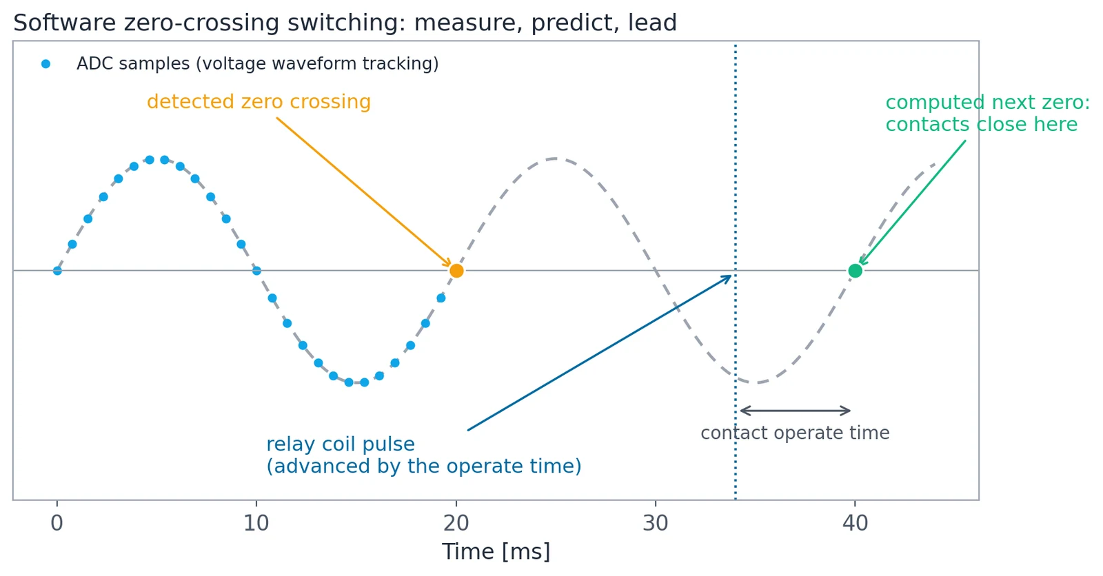
The lead time is the critical part. An electromagnetic relay does not act instantly: several milliseconds pass between the coil pulse and the physical closing of the contacts. The module accounts for this delay, so the coil receives its signal early and the contacts reach the closed position exactly as the voltage passes through zero.
The whole process runs locally in the module, independently for each channel, with no extra wiring and with no involvement of the Hub in the switching timing itself.
Zero-crossing switching applies to AC loads only. With 24 V DC loads the outputs behave as conventional relays. For strongly inductive loads, the load categories and current limits from the module datasheets still apply, because the current there is phase-shifted relative to the voltage.
# What contact degradation looks like: photos from our tests
Before selecting relays for the I/O and RELAY modules, we ran a series of inrush current endurance tests. Candidate relays switched loads with high inrush currents, and after the test cycles we cut their housings open and inspected the contact surfaces under a microscope.
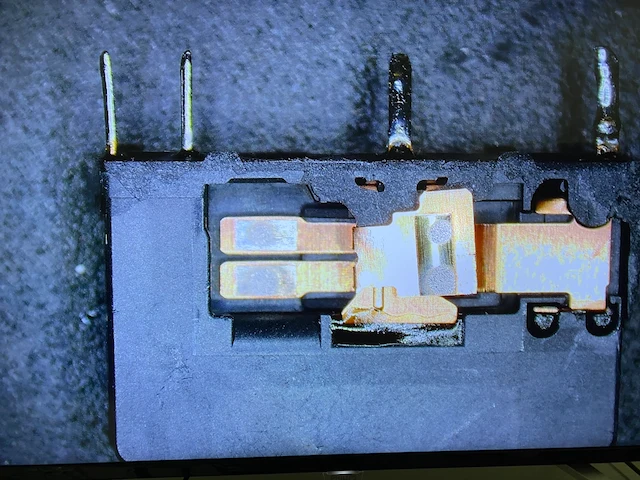
The differences between units were clear. Contacts poorly matched to the load characteristics, or switched at a random phase of the sine wave, showed severe surface degradation: melted spots, craters, and deposits left by arc discharges.
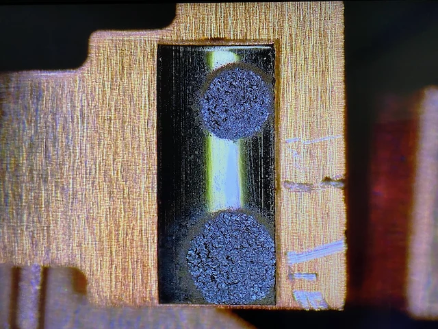
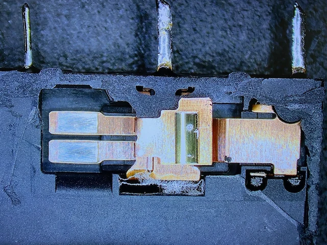
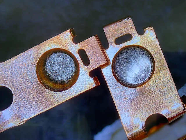
The comparison below shows the difference directly: on the left, a contact with a surface destroyed by arcing; on the right, a contact with a smooth, even surface after a comparable number of cycles under gentler commutation conditions.
The test conclusions fed directly into the module design. First, we selected relays with contacts rated for high inrush currents (up to 80 A for 20 ms per contact in the RELAY module). Second, every AC channel switches at the voltage zero. The combination keeps contact erosion to a minimum and significantly extends contact life.
# What the user gains
In short: the same relay survives far more cycles with demanding loads. In practice this translates into a few concrete outcomes.
Longer installation life. Electric heating controlled by a thermostat performs hundreds, and in intensive scenarios up to a few thousand, switching cycles per year, all under full load. Switching at the zero crossing removes the surge from every one of those cycles, so the contacts degrade many times slower. The RELAY module switches circuits up to 16 A (category AC1) and is intended precisely for heaters, heating mats, and socket circuits.
Safe control of LED lighting. LED drivers have a capacitive input and high inrush currents. They are the most common cause of welded contacts in conventional installations. Switching at the zero limits the capacitor charging current to a gradual rise along the sine wave.
Less interference on the line. Commutation at zero voltage produces no steep di/dt edges, so the installation receives no impulses that could disturb electronics in other circuits.
Fewer service visits. A welded relay in a distribution board means calling the installer and replacing the module. Removing the main wear mechanism reduces the number of such interventions. In addition, both modules measure output current (RELAY per channel, I/O per group of four relays), so unusual consumption is visible in Voldeno Mobile before a failure occurs.
From the installer's perspective, nothing changes in how a project is designed: the same DIN rail modules, the same configuration in Voldeno Studio, the same Voldeno Bus. Zero-crossing switching simply works in the background, on every cycle of every AC output.
# Further reading
- Modules with zero-crossing switching: RELAY, I/O
- Bus topology and wiring
- Voldeno system overview
- RELAY module wiring documentation