# Relay Module Wiring
Work on RELAY module terminals involves high-power field circuits at 230 V AC or 24 V DC. De-energize field wiring before connecting conductors. Installation must be carried out by a qualified electrician in accordance with local regulations. Protect each circuit with an appropriate fuse or circuit breaker.
This guide covers Voldeno RELAY module (REL-A-D-1) wiring: the terminal map, connecting four independent high-power relay outputs, and the Voldeno Bus connector. Electrical ratings and use cases are on the RELAY product page.
# Module overview
The 4-DIN RELAY module switches high-power loads in a Voldeno installation:
| Area | Channels | Summary |
|---|---|---|
| Relay outputs | 4 (O1–O4) | NO contacts, up to 16 A per channel (AC1), per-channel current measurement |
| Bus | 1 × Voldeno Bus | 24 V DC supply, GND, CAN-FD (BUS+, BUS−) |
Unlike the I/O module, RELAY has no digital inputs. It is used only for field circuits: electric heating, grouped lighting, mains sockets, blinds, and drives with a high inrush current.
# Terminal map
Load terminals are on the top edge of the module; the bus connector is on the bottom.
# Top row: relay outputs
Terminal order (left to right):
| Terminal | Function |
|---|---|
| I1 | Channel 1 input (common line before the contact) |
| O1 | Channel 1 output (to the load) |
| I2 | Channel 2 input |
| O2 | Channel 2 output |
| N | Neutral conductor voltage reference (sense only, does not carry load current) |
| L | Line voltage reference (sense only, does not carry load current) |
| I3 | Channel 3 input |
| O3 | Channel 3 output |
| I4 | Channel 4 input |
| O4 | Channel 4 output |
Each channel is an Ix / Ox pair. The relay closes an NO contact between Ix and Ox when the output is turned on in logic. Load current flows only through the Ix–Ox pair: connect line (or DC positive) to I1–I4, and O1–O4 to the load. Run the load return (AC neutral conductor or DC negative) to panel terminals.
Terminals L and N are voltage references only for mains tracking and software zero-crossing switching.
- AC loads: connect L to line and N to the neutral conductor on the same mains system that feeds the switched circuits (reference for zero detection only).
- DC loads: you do not need to connect L and N. Optionally connect DC field circuit poles under them if you need to detect whether voltage is present on the sense terminals.
# Bottom row: Voldeno Bus
| Terminal | Function |
|---|---|
| 24V | Module supply from the bus |
| GND | Bus ground |
| BUS+ | CAN High |
| BUS− | CAN Low |
Bus topology, termination, and length limits are described in Bus topology and wiring.
# Connecting loads
Outputs are NO (normally open) contacts with high inrush support. The module is intended for loads that exceed the I/O module ratings.
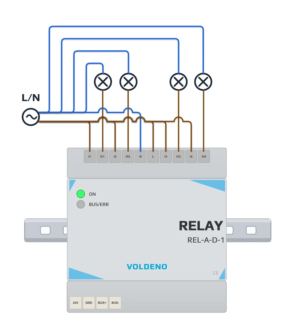
AC example (four lighting circuits):
- Connect the switched circuit line to I1, I2, I3, and I4 (shared line with jumpers or separate circuits per your design).
- Connect O1, O2, O3, or O4 to the other side of each load according to the channel mapped in Voldeno Studio.
- Run each load return (neutral conductor) to the neutral bus in the panel.
- For zero-crossing switching, connect L to line and N to the neutral conductor as voltage references (see Zero-crossing switching).
- Protect each circuit with an appropriate fuse or circuit breaker in the panel.
Each channel is independent: you can control four separate circuits from one module as long as each stays within the per-channel current limits.
# Current limits
| Load category | Max current | Voltage / power |
|---|---|---|
| AC1 (resistive, cos φ = 1) | 16 A | 250 V AC |
| AC15 (inductive, cos φ = 0.4) | 1.5 A | 240 V AC |
| AC3 (AC motors) | 750 W | 240 V AC |
| DC1 (resistive) | 16 A | 24 V DC |
| DC13 (inductive, L/R = 7 ms) | 0.22 A | 120 V DC |
Minimum switching power: 1 W. Inrush closing current: 80 A / 20 ms.
For inductive loads (motors, transformers, solenoid valves) use AC15 or AC3 categories and derate as needed. For LED drivers with high inrush current, the RELAY module is the right choice instead of I/O channels.
# Current measurement, protection, and zero-crossing switching
The module measures current separately on each channel (four independent sensors). Values are available in Voldeno Studio and Mobile after outputs are configured.
A built-in temperature sensor protects the module from overheating during sustained load. The enclosure is ventilated for better heat dissipation.
For AC loads, channels use software zero-crossing switching. The module tracks the sine wave on reference terminals L and N and closes contacts near 0 V. Without L/N connected on AC loads, zero-crossing does not run; on DC-only loads those terminals are not required. Technical background is in Zero-crossing switching on I/O and RELAY modules.
# Installation sequence
- Mount the module on the DIN rail in the panel. Power the Voldeno Bus according to bus topology.
- Connect 24V, GND, BUS+, and BUS− to the adjacent module or bus segment.
- Confirm in Voldeno Studio that module REL-A-D-1 appears in the device list.
- With field circuits de-energized, connect line to I1–I4, loads to O1–O4, and returns to the panel bus. For AC loads, wire L and N as voltage references; for DC-only loads you may leave L/N unconnected.
- In Studio, map each output channel to a register that matches the actual wiring.
- Test each channel: output switching, current measurement, and module temperature under load.
# Questions and answers
How does RELAY differ from the I/O module?
I/O combines 8 digital inputs and 8 low-power outputs (up to 5 A per channel and per group). RELAY provides 4 high-power outputs (up to 16 A per channel in AC1) with per-channel current measurement. It has no digital inputs.
Does each channel need its own fuse?
Yes. Protect each field circuit fed through the RELAY module according to regulations and the load rating. The module switches the circuit; it does not replace overcurrent protection in the panel.
Can I connect a 3 kW heater on one channel?
At 230 V AC, a 3 kW heater draws about 13 A. That fits within the 16 A (AC1) per-channel limit for a resistive load, provided the circuit is correctly protected.
When should I use AC3 instead of AC1?
AC3 applies to AC motor loads (pumps, drives). Power up to 750 W at 240 V AC. For motors and transformers, check the datasheet and derate as required.
Is RELAY suitable for LED lighting with drivers?
Yes. That is one of the main use cases: circuits with high inrush current and grouped lighting sections that exceed I/O module limits.
What are the L and N terminals for?
Voltage reference only for AC mains zero detection. On DC-only loads you may leave them unconnected or wire DC field circuit poles under them if you need to detect whether voltage is present on the sense terminals.
# Next steps
- RELAY module — specifications and use cases
- I/O module wiring — digital inputs and low-power outputs
- Define logic in Voldeno Studio — map channels to logic blocks
- Bus topology and wiring