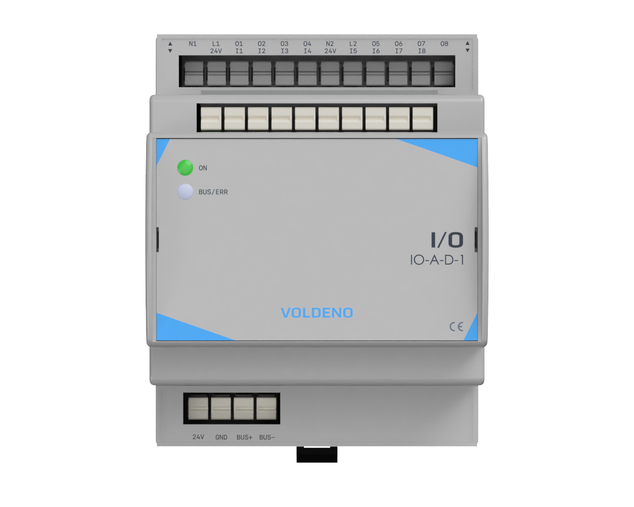
IO-A-D-1
I/O
PLN 899.00incl. VAT
The I/O module allows control of any low-power electrical device such as lights, valves or gates, and connects up to eight digital inputs to the system, e.g. wall switches or window reed contacts.
At a glance
8
digital inputs or frequency counters
8
low-power relay outputs
250 VAC / 5 A
per relay group
DIN rail
push-in terminals, fast installation
Voldeno Bus
24 V DC, power and data
Current measurement
per group of 4 relays
What it does
Switches and lighting
Connects standard wall switches to digital inputs and controls lighting sections via relay outputs with independent current measurement per group.
Gates, windows and motion
Integrates reed contacts, motion sensors and gate position signals into the system, providing the foundation for access automation, alarms and presence-based scenes.
Pulse counting and metering
Digital inputs can operate as hardware frequency counters (up to 250 Hz), enabling connection of S0 energy meters, flow meters and analog wind sensors.
Gates, valves and contactors
Relay outputs are suited for controlling gates, irrigation solenoid valves, electric door strikes and external contactors. Two fully isolated groups of four channels guarantee separation of independent circuits.
Full technical specifications
Inputs
- Number of channels
- 8
- Type
- Digital, voltage-activated 24 V DC
- Auxiliary outputs
- 2 × 24 V DC for use with push buttons and dry contacts
- Frequency counter
- Up to 250 Hz in frequency counter mode
Outputs
- Number of channels
- 8 independent relay outputs in 2 isolated groups (4 + 4)
- Contact type
- NO (normally open)
- Rated load voltage
- 230 V AC or 24 V DC
- Max current - AC1
- 5 A / 250 V AC (cos φ = 1); limit per relay and per whole 4-output group
- Max current - AC15
- 2 A / 250 V AC (cos φ = 0.4); limit per relay and per whole 4-output group
- Max current - DC1
- 5 A / 30 V DC (cos φ = 1); limit per relay and per whole 4-output group
- Max current - DC13
- 2 A / 30 V DC (L/R = 7 ms); limit per relay and per whole 4-output group
- Min switching power
- 0.05 W (10 mA at 5 V DC)
- Current measurement
- 1 current sensor per group of 4 channels (2 sensors total)
Power supply
- Supply
- 24 V DC via Voldeno Bus
- Terminal type
- Push-in
- Wire cross-section
- 0.2 … 0.75 mm² (24 … 18 AWG)
Communication
- Bus
- Voldeno Bus (BUS+, BUS−, GND)
Mechanical
- Mounting
- Distribution panel on 35 mm DIN rail
- Size (DIN):
- 4
- Dimensions (H / W / D)
- 91 / 36 / 62 mm
- Weight
- 157 g
Environmental
- Operating temperature range:
- 0 - 45 °C
Certifications
- Marking
- CE, RoHS
- Installation
- By a qualified electrician in accordance with local regulations
Connections and wiring
Terminal numbering, bus pinout and example circuits are documented in the wiring guide. Always de-energize field wiring before working on terminals.
- Inputs: connect push buttons or dry contacts between the channel input and reference per the terminal map (see wiring guide).
- Outputs: relay NO contacts switch the load. The same current limit applies to each relay and to the whole 4-output group: 5 A for resistive AC1/DC1, 2 A for inductive AC/DC at the stated cos φ or L/R; derate further if needed.
- Relay groups: the two groups of 4 relays are fully isolated from each other - they can be used for independent circuits or different voltage levels.
- Voldeno Bus: use BUS+, BUS−, and GND from the Hub or bus segment; keep bus topology within project limits.
- Grounding: follow the panel earthing concept and manufacturer notes for SELV/field separation.
Ecosystem integration
The I/O module connects to the Voldeno Bus alongside other extension modules. Each input and output is configured in Voldeno Studio - automation logic, schedules and circuit states are then available in Voldeno Mobile.
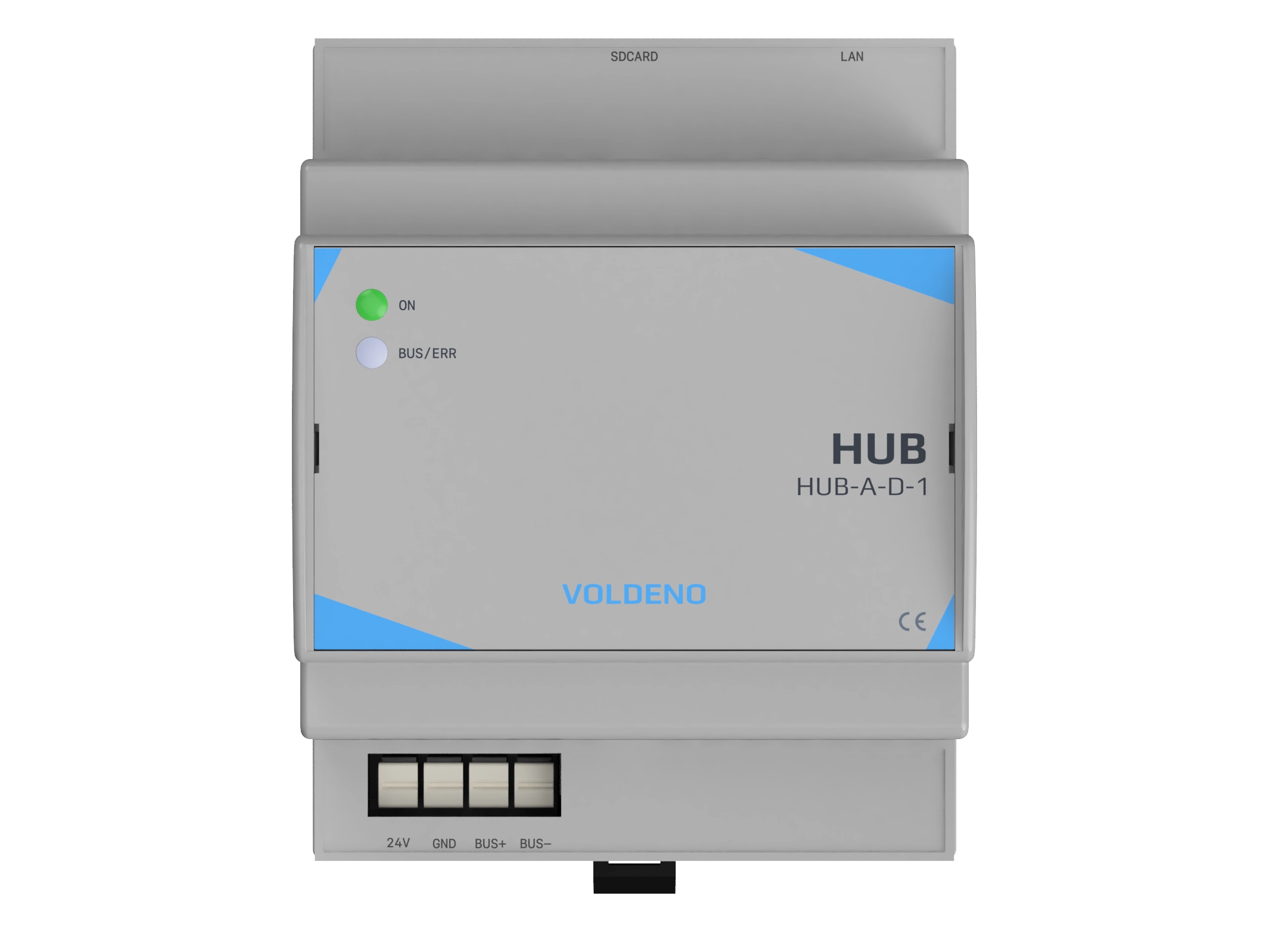
Requires a Voldeno Hub on the same installation.
In the box
- 1× I/O module (IO-A-D-1)
- Information leaflet
- Factory packaging
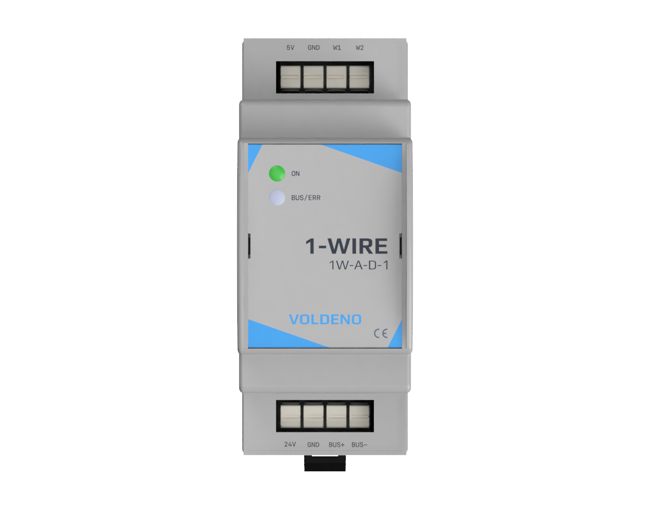
Related products
Modules that pair well with I/O in the same panel.
Voldeno I/O is the module for connecting the physical world to a Voldeno installation. Eight digital inputs support wall switches, push buttons, reed contacts, motion sensors and pulse meters. Eight relay outputs switch lighting, valves, gates and small loads - with current measurement per relay group. Every input and output is configured individually in Voldeno Studio.
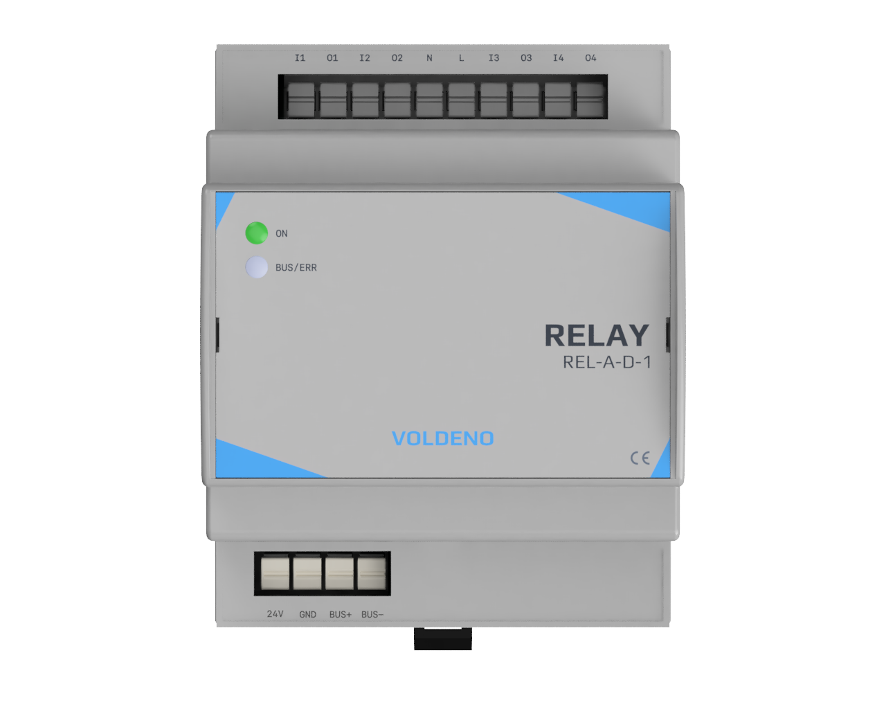
The eight relay outputs are split into two fully isolated groups of four channels. Each channel switches up to 5 A, with the same 5 A limit per group. The I/O module suits lighting sections, valves, gates and similar loads - for applications requiring higher switching current, such as electric heating, high-power LED drivers, blinds or mains socket circuits, the RELAY module is the right choice.
Your next step starts here.
Order the module, consult us about your project, or review the technical documentation before deployment.