# How to define logic in Voldeno Studio from scratch
This guide explains how to define logic in Voldeno Studio once installation is done: modules are on the DIN rail, the Voldeno Bus is up, and Studio shows devices with correctly mapped registers. From there you build automation in the block editor, test it locally, deploy it to the Hub, and hand control to the end user through Voldeno Mobile.
If you have not installed Studio yet, start with Voldeno Studio — installation and overview. For terminology (Hub, registers, logic blocks) see Core concepts.
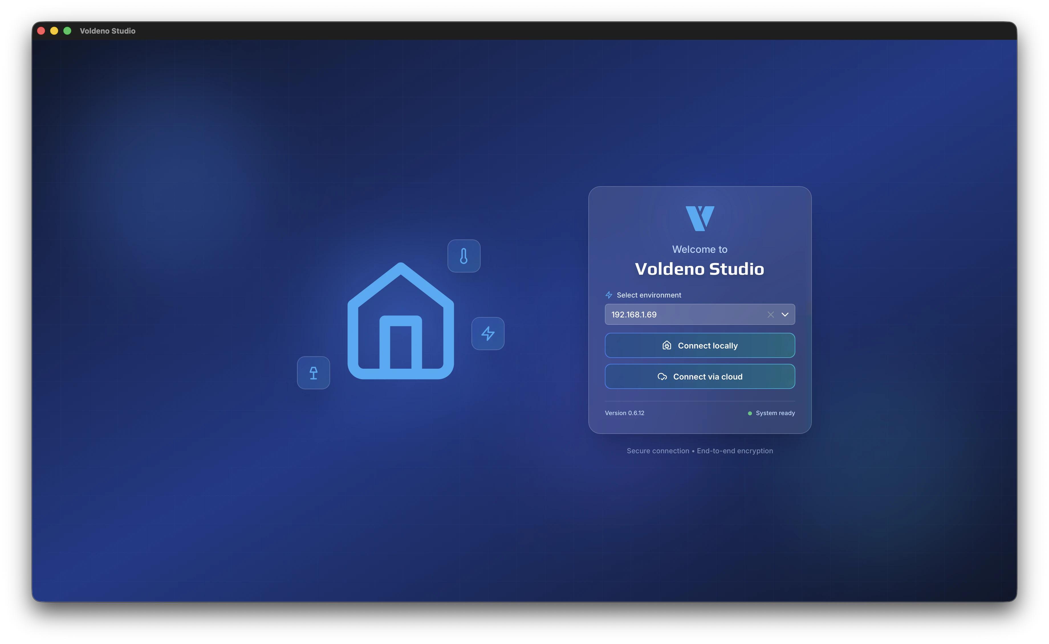
# Connect to the Hub on the local network
- Launch Voldeno Studio on a computer in the same LAN as the Hub.
- The start screen lists Hub addresses detected on the local network. Discovery uses mDNS queries — you do not need to enter an IP manually unless your router blocks multicast.
- Select the correct Hub and connect.
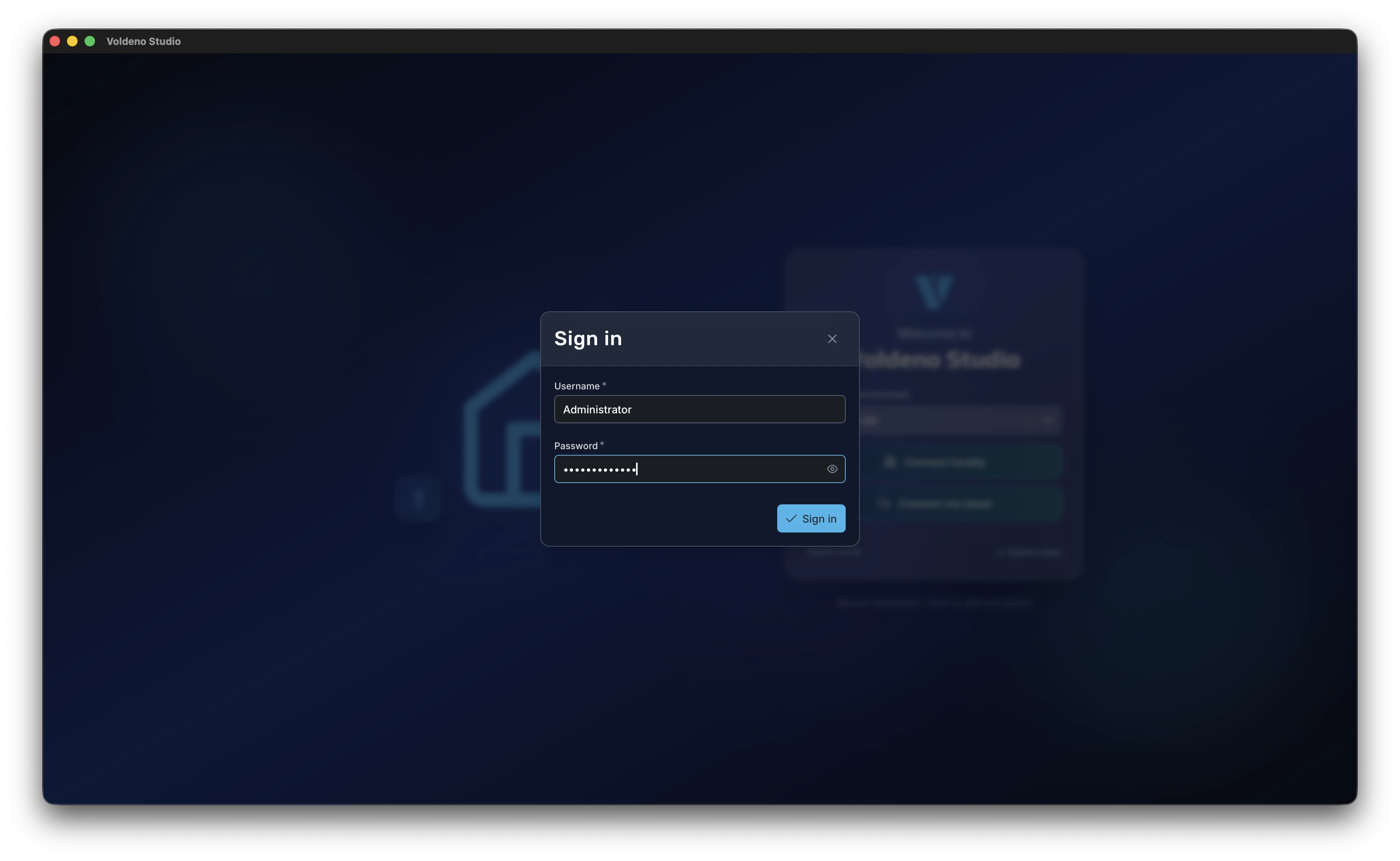
# Sign in
On the first connection to a given installation from this Studio instance, you enter the username and password configured on the Hub. Studio then stores secure tokens — on later sessions you are signed in automatically without re-entering the password.
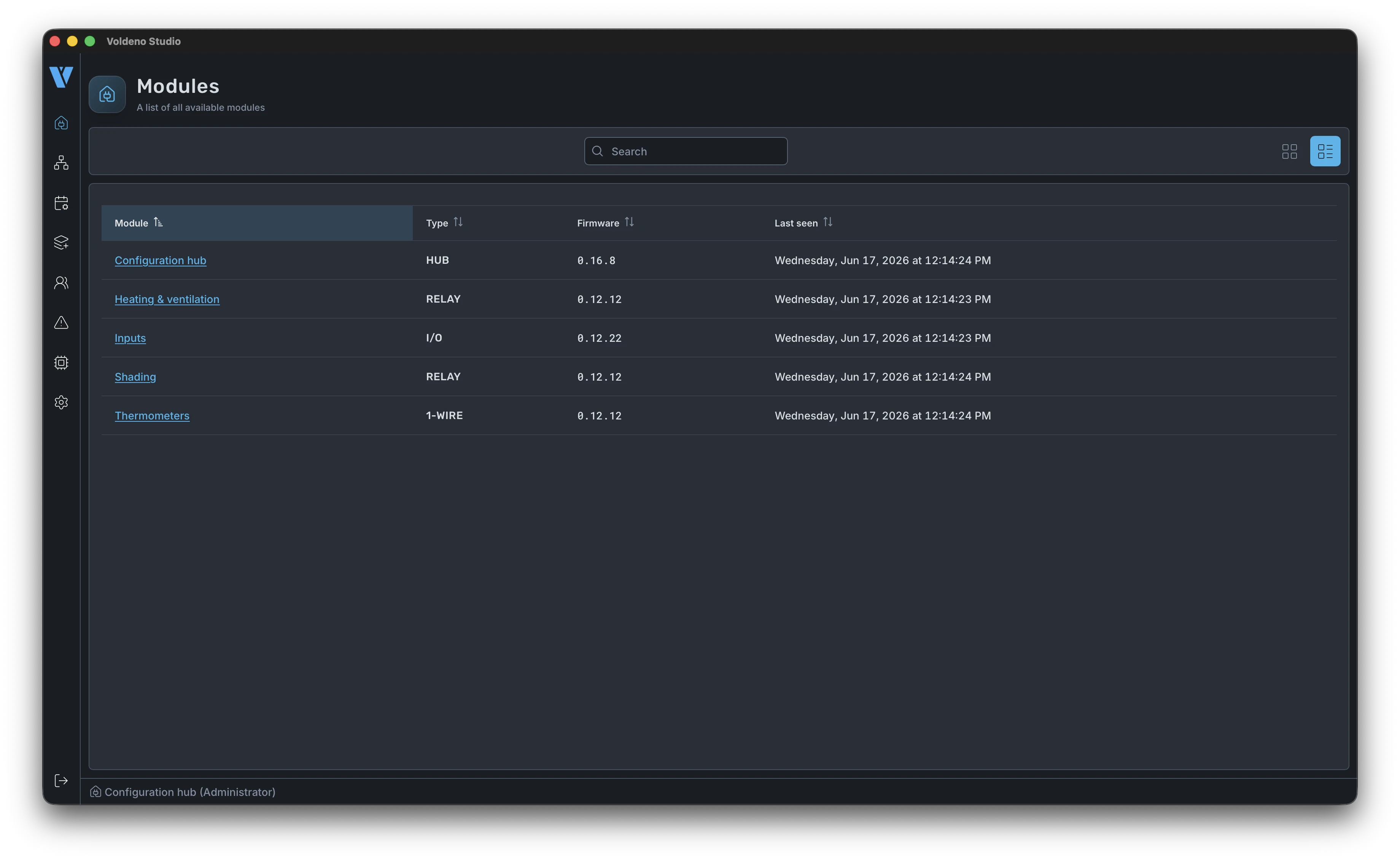
# Verify hardware modules
After sign-in, Studio shows the list of modules visible on the bus: I/O, RELAY, 1-WIRE, ANALOG INPUT, and others. Treat this as a checkpoint — every input and output channel should map to a register that matches the actual wiring. If something is missing, fix bus diagnostics before building logic.
# Logic editor and groups (tabs)
You define logic in the block editor. On first open you see an empty canvas — that is expected until you add rules.
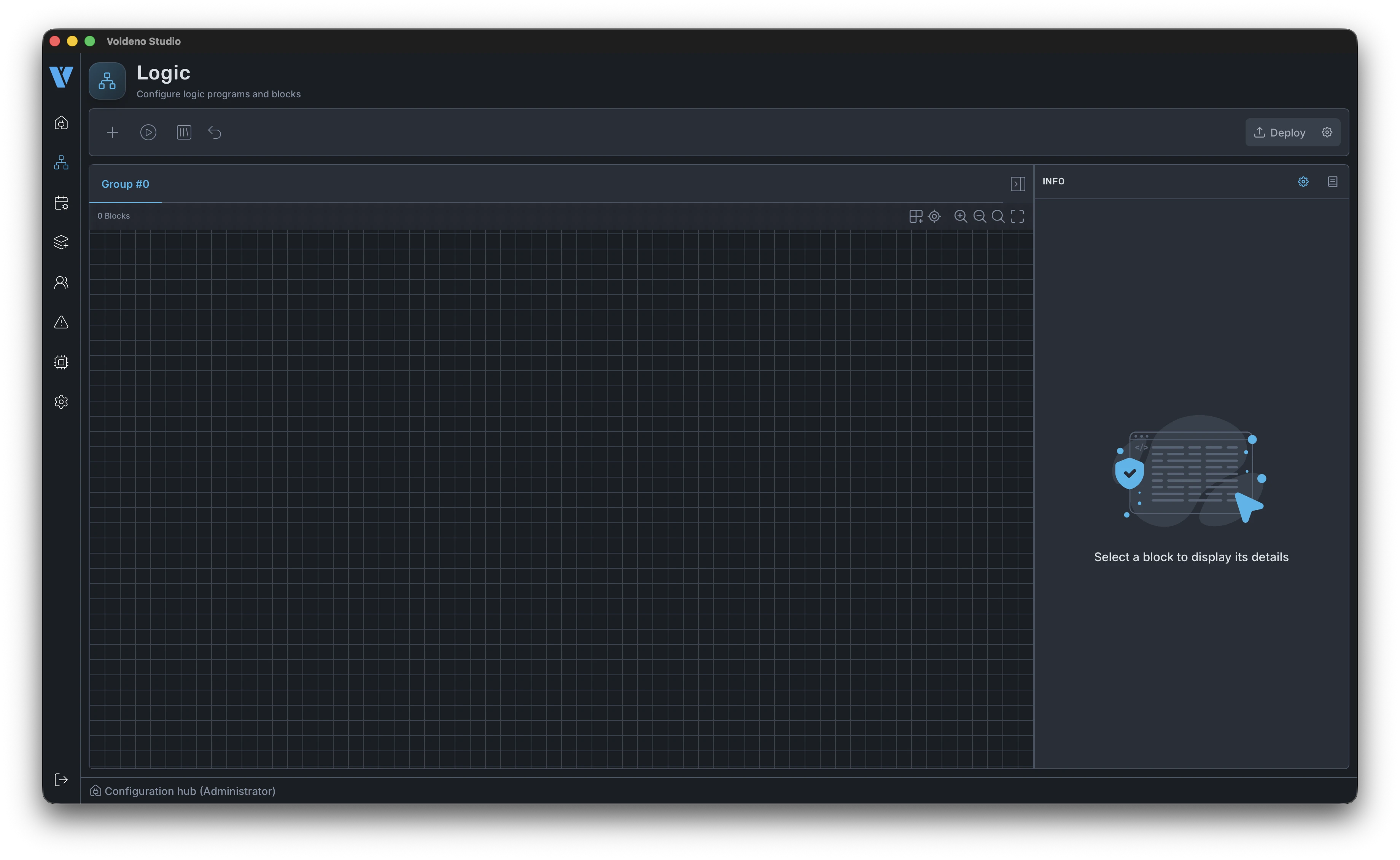
Before adding the first block, split the project into groups. Each group is a separate tab in the editor — typically one per installation area: lighting, heating, blinds, gate, irrigation. Large projects stay readable, and you can edit and test sections independently.
- Open the group menu (tabs at the top of the editor).
- Add a new group.
- Name it for its scope, e.g.
Lights,Heating,Shading.
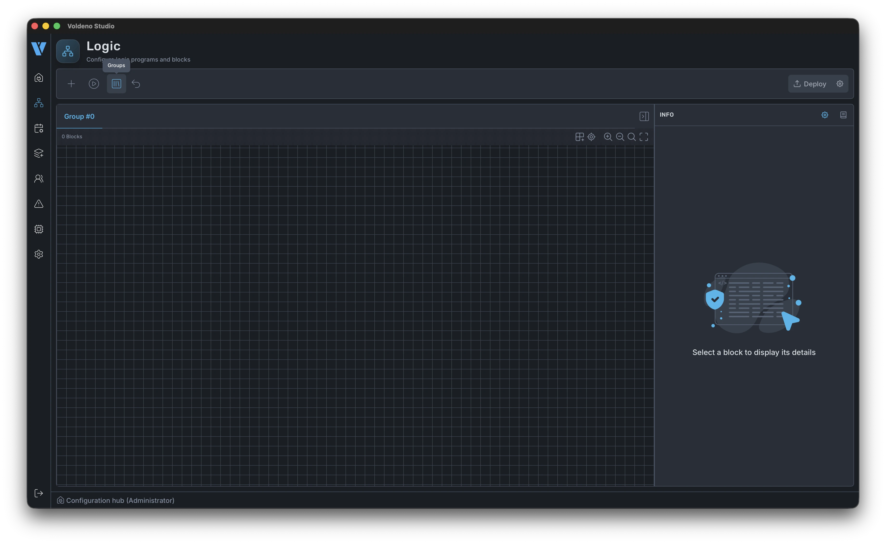
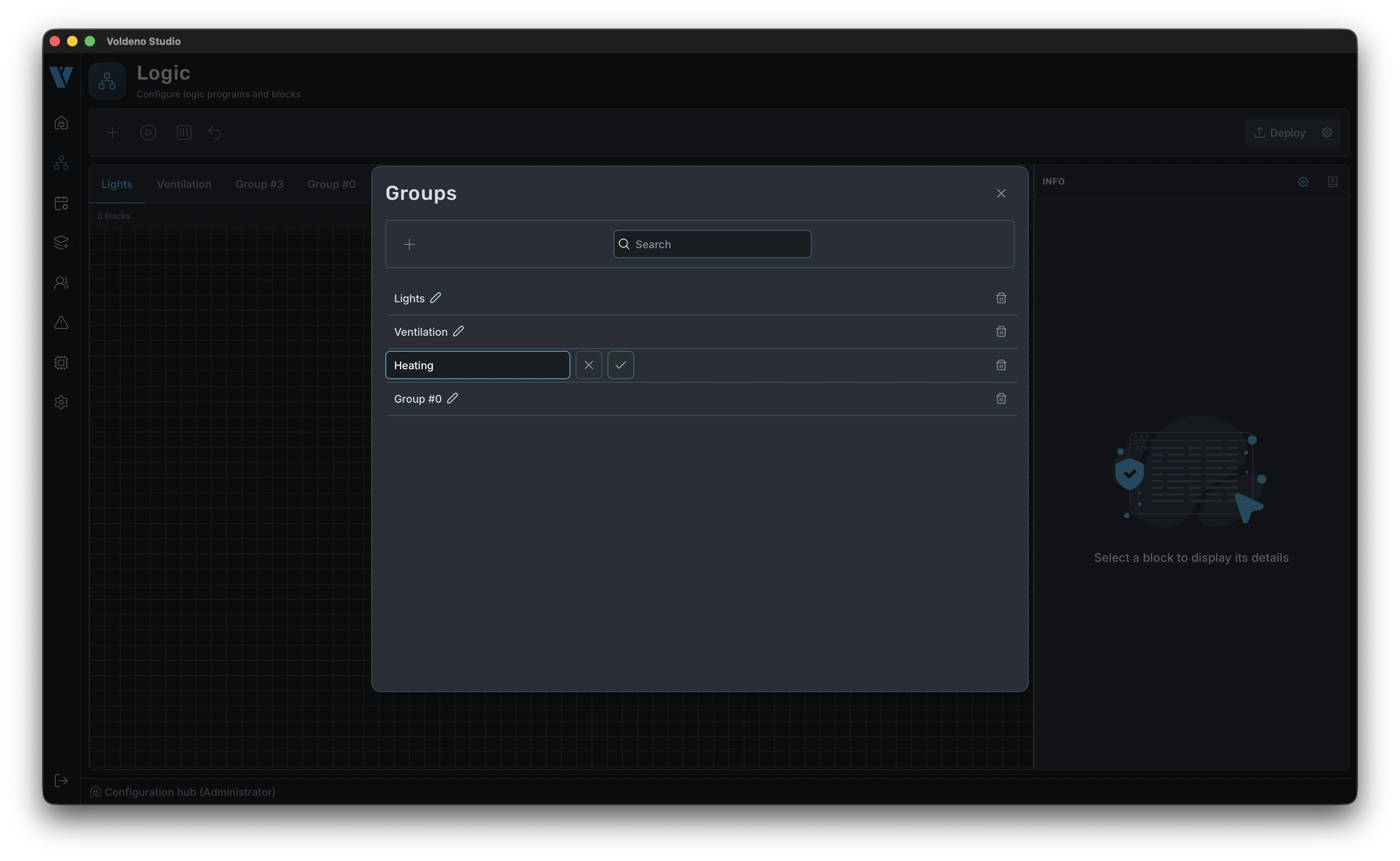
Once groups exist, each tab has a canvas ready for work. Below is an empty Lights group — from here you build rules for that part of the installation.

# Adding and configuring logic blocks
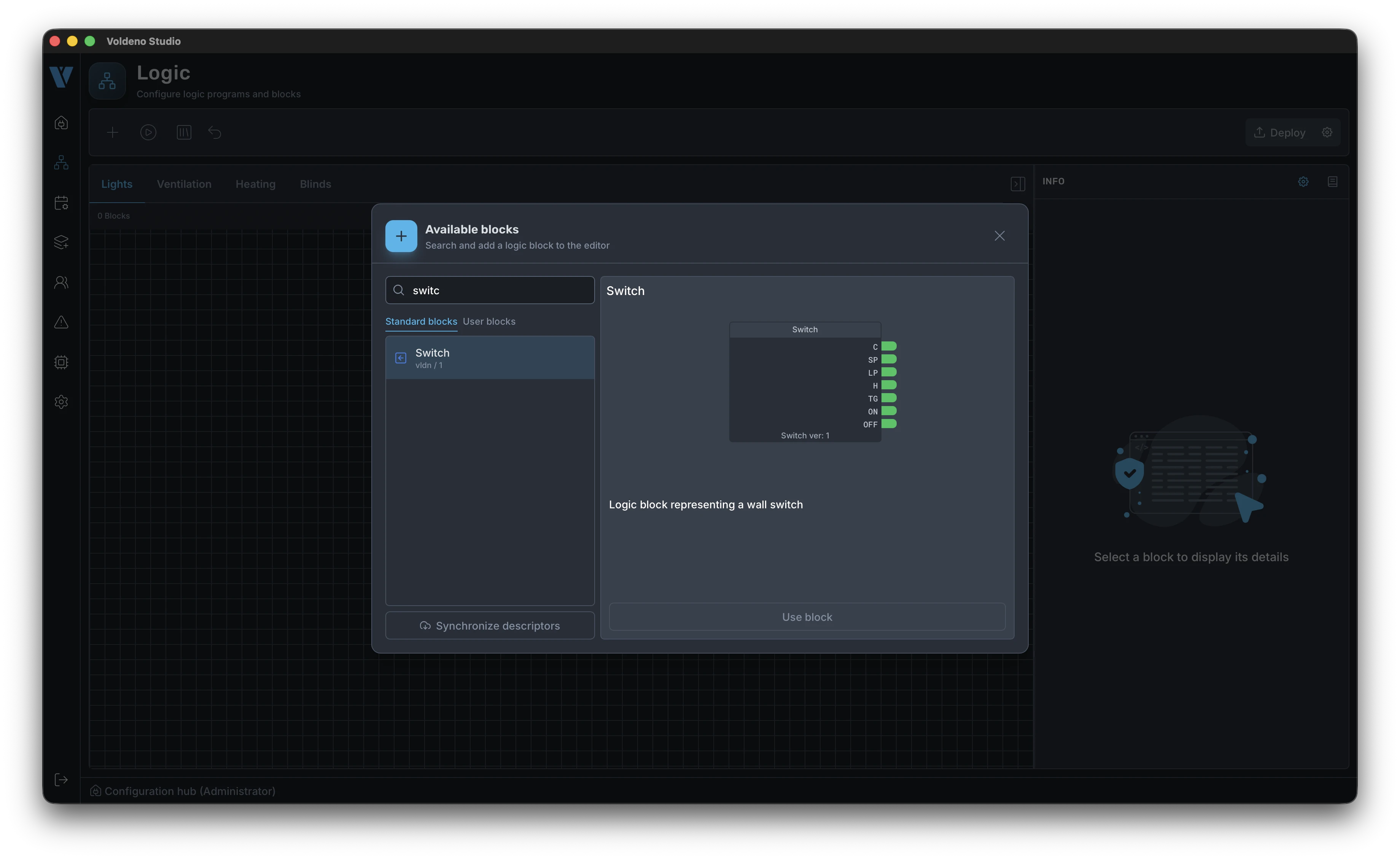
Logic blocks are ready-made automation elements: switches, scenes, regulators, counters, integration bridges. You connect them with wires — an output of one block to an input of another.
- Click the + icon in the editor menu.
- In the picker, find the right block (e.g. light control, thermostat, blind drive).
- Click the block — the cursor enters drag mode. Drop the block on the canvas where it belongs in the diagram.
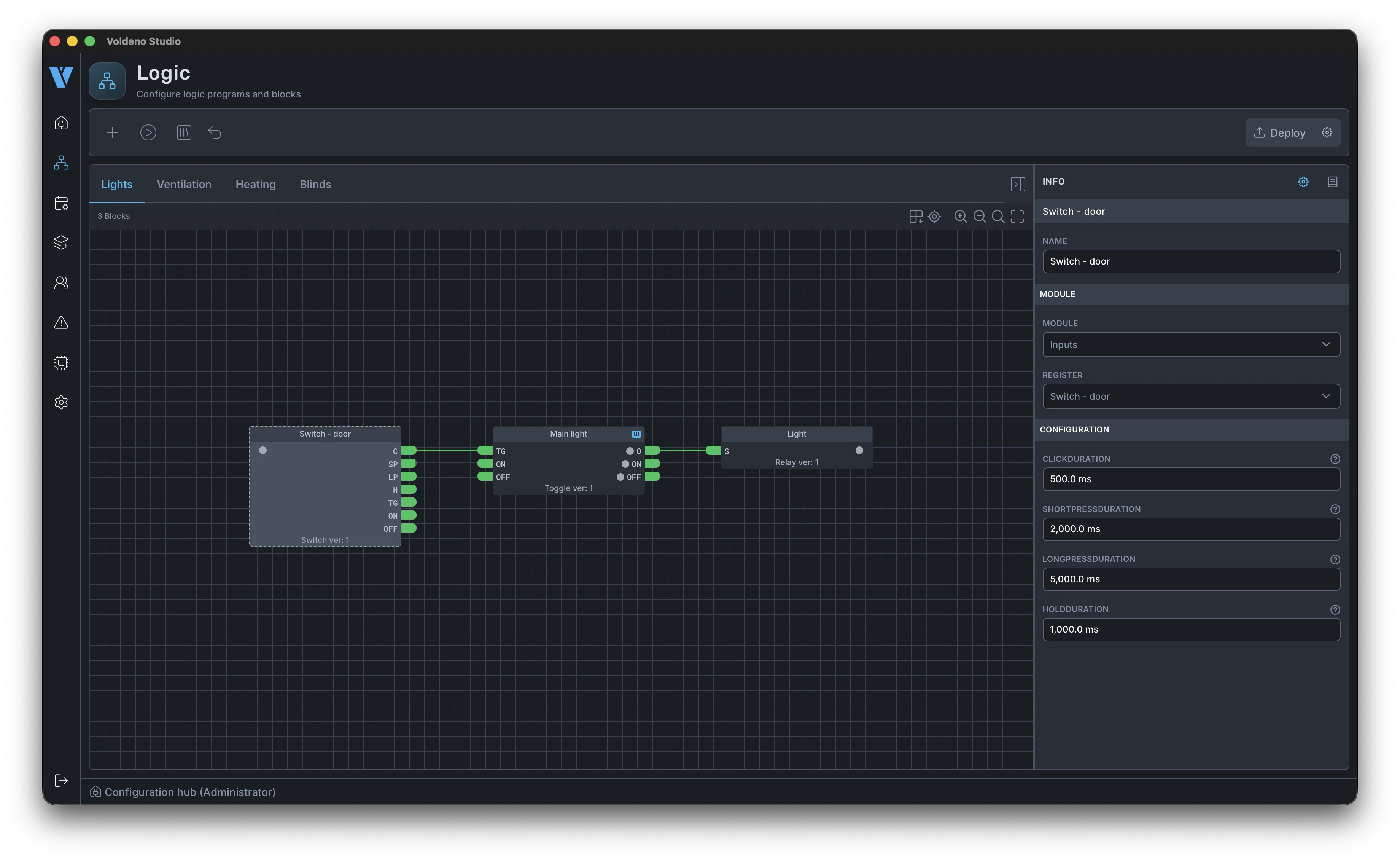
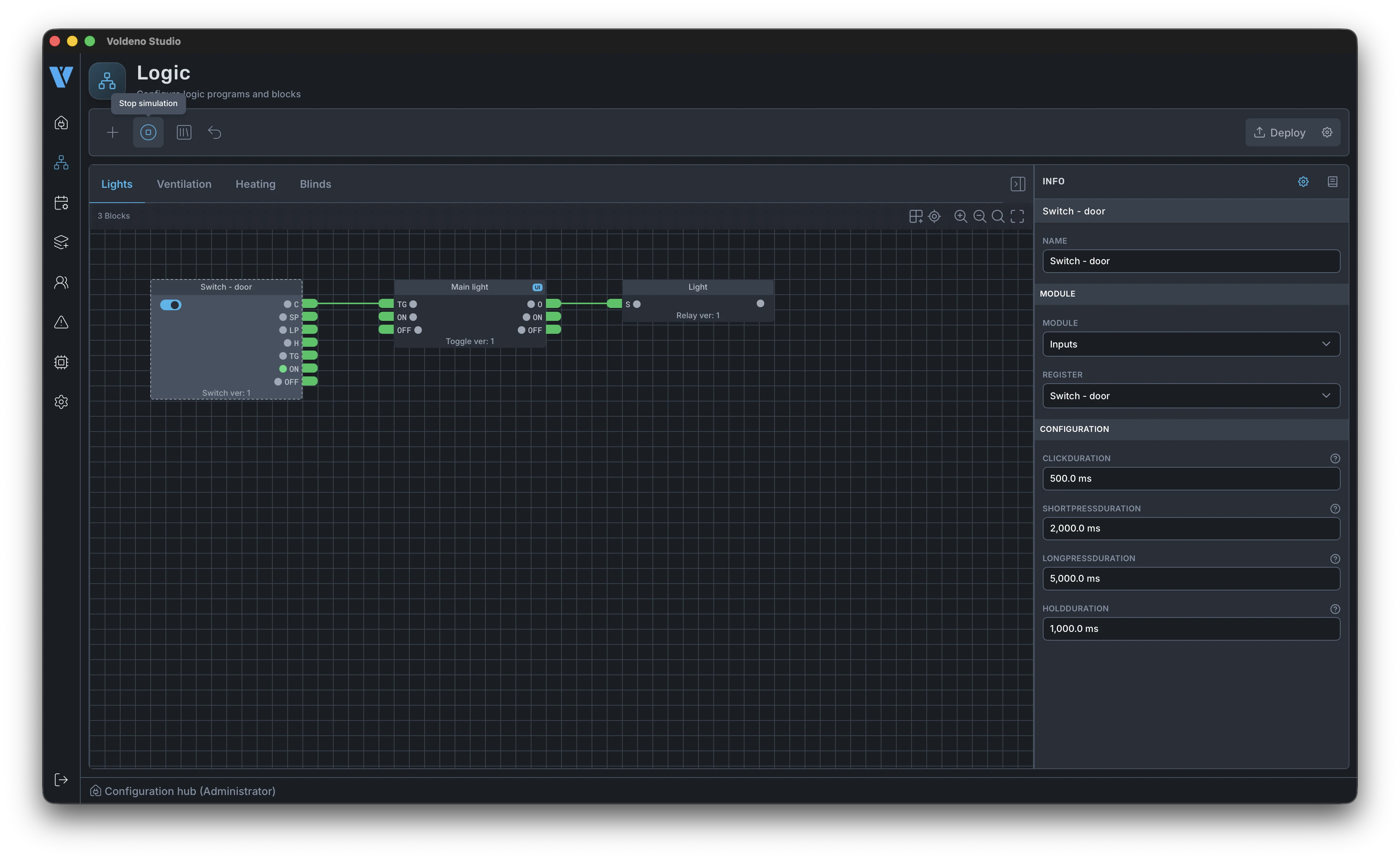
Every block needs configuration: inputs and outputs linked to module registers on the bus. In the properties panel you pick the specific I/O channel, RELAY output, 1-Wire sensor, or analog input that matches the circuit in the distribution board.
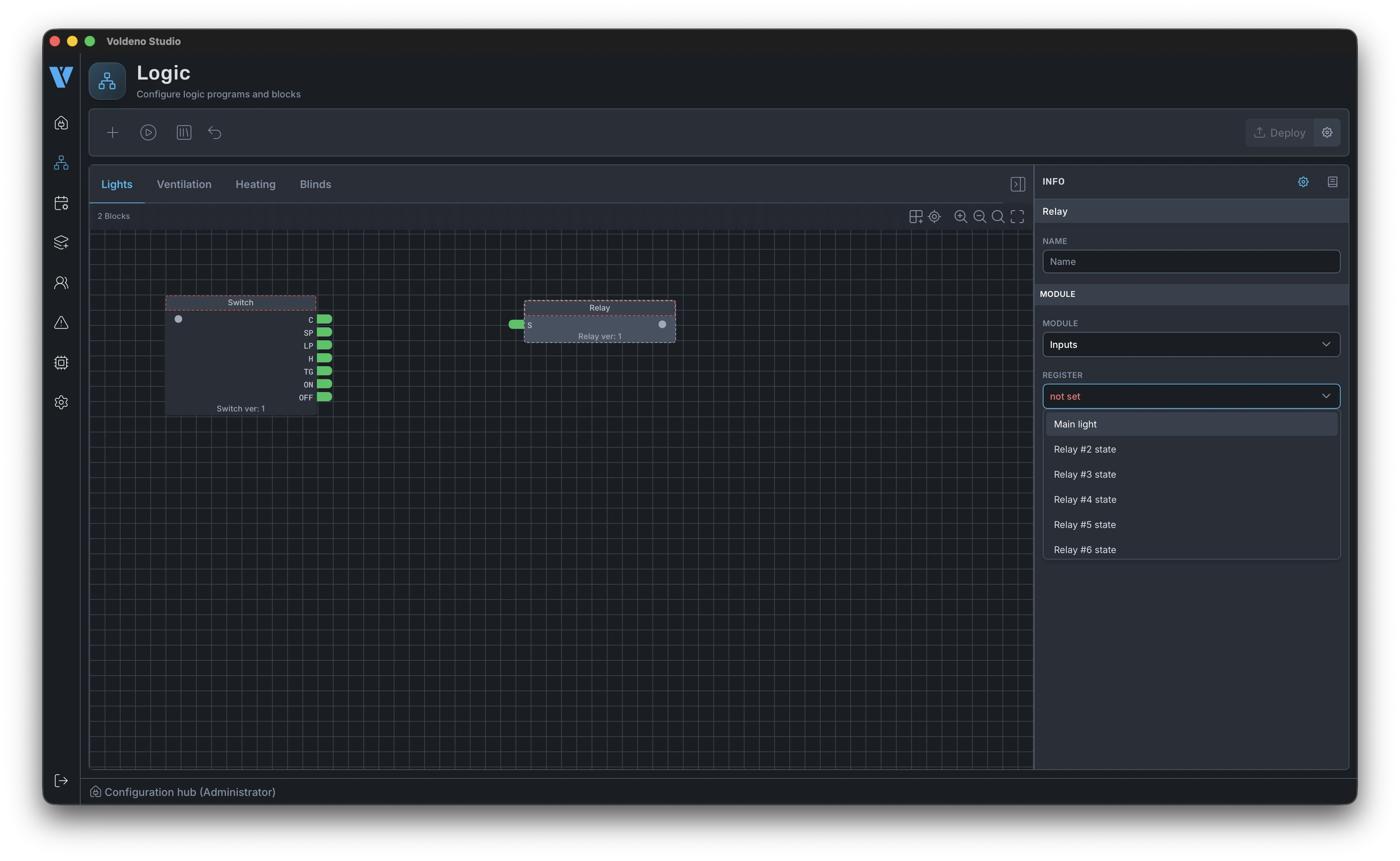
In the example below, a lighting block has the button input and relay output set. Parameters (e.g. toggle mode, off delay) are edited in the same panel without leaving Studio.
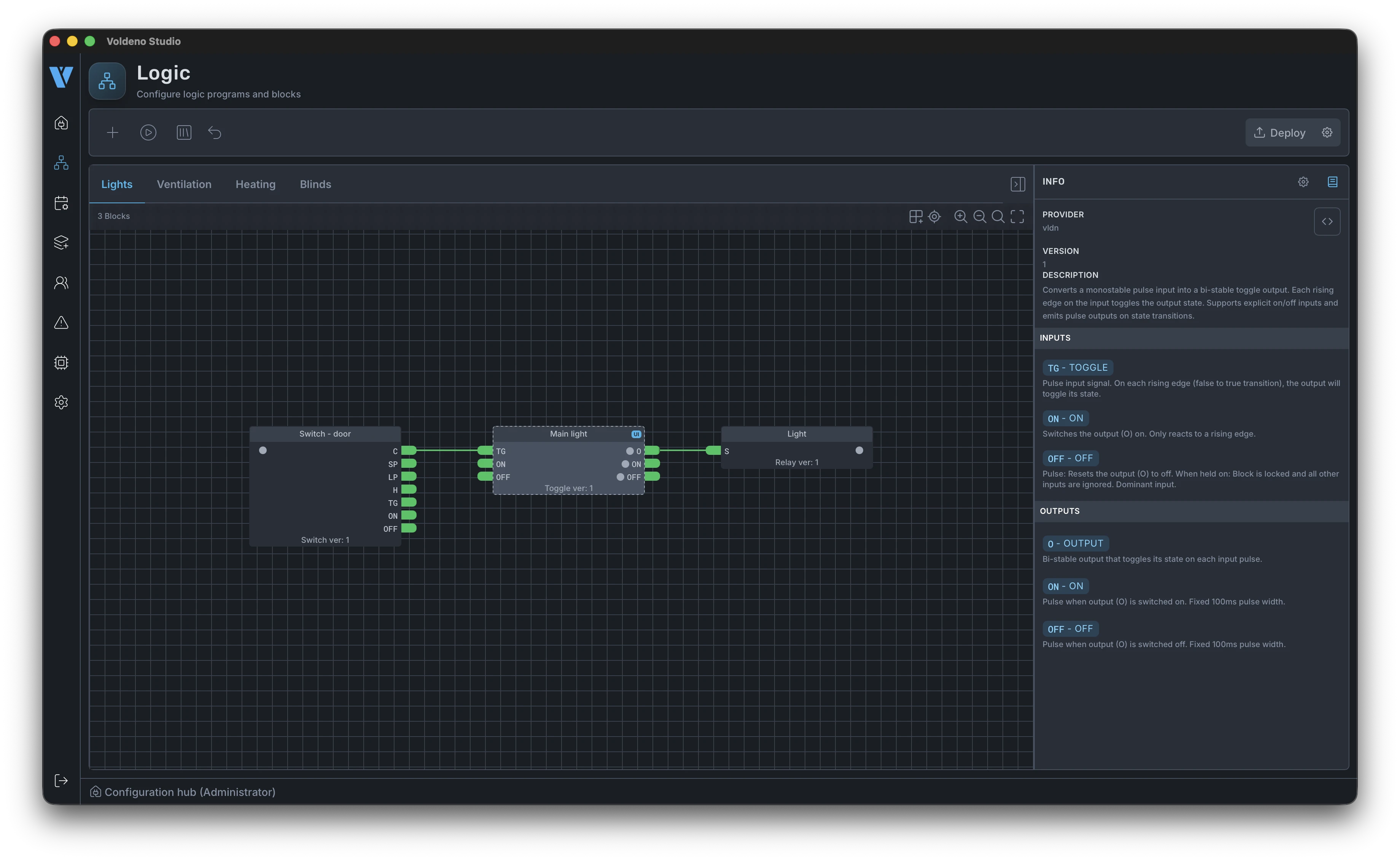
# Block documentation and source code
Every logic block has built-in documentation in Studio — input and output descriptions and typical use cases. You open it from the editor without switching to a browser.
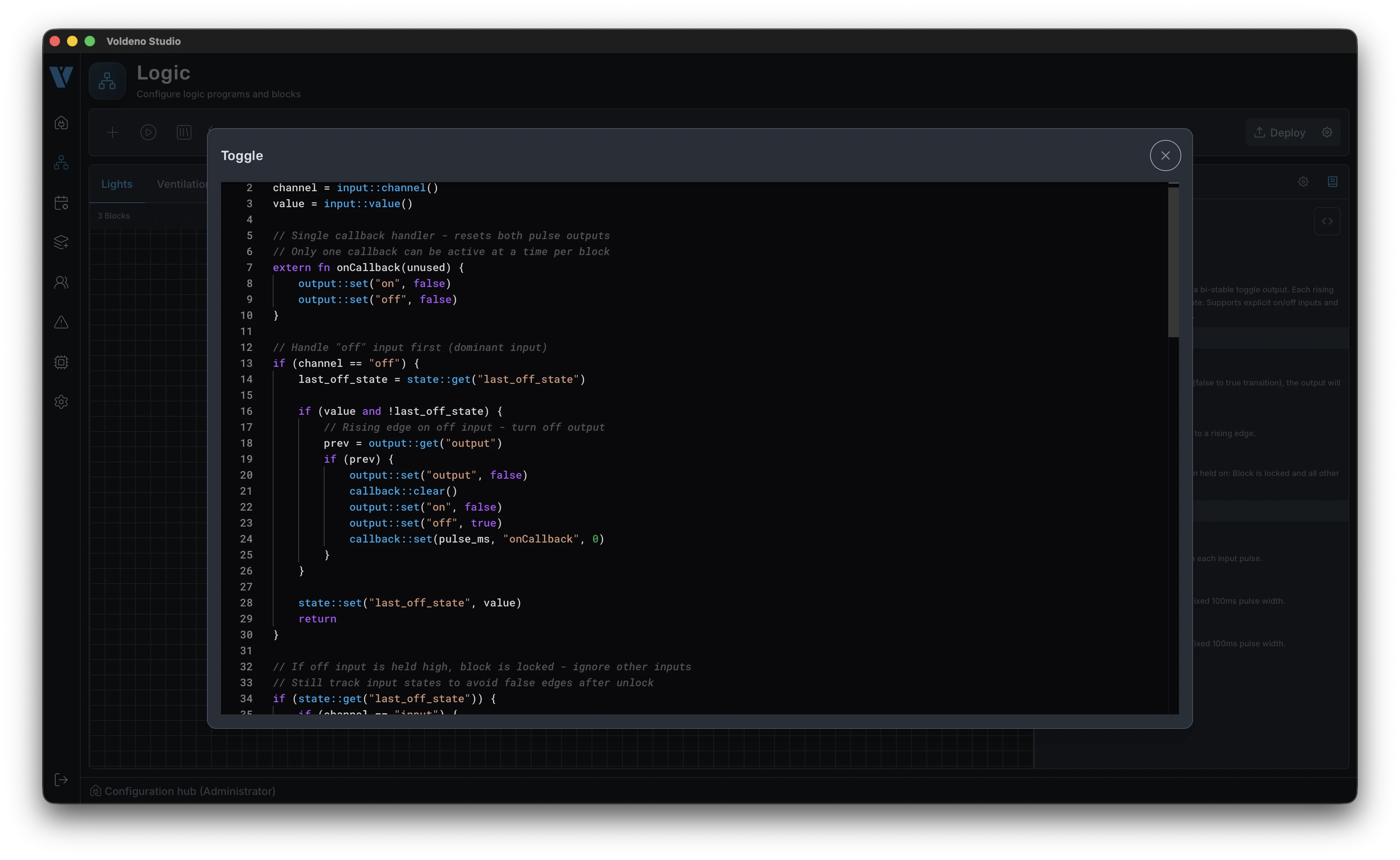
When you need more detail or want to see exactly what the Hub executes, you can view the block source code (Volang) inside Studio. That helps with debugging and custom extensions — see Volang and VolangVM for the language overview.
# Further logic sections and simulation
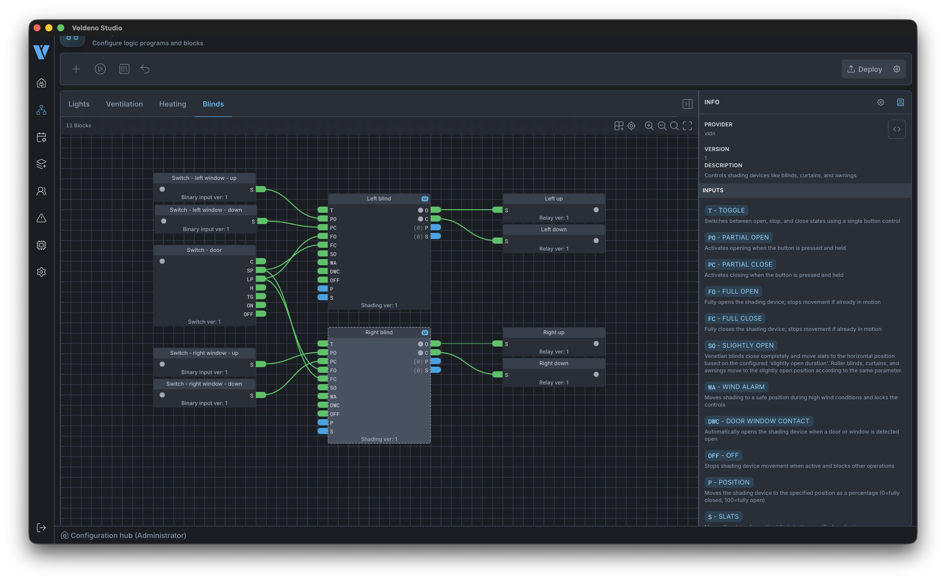
Repeat the same pattern in the remaining groups. Below is a shading section (Shading): drive, position, and condition blocks are wired and mapped to specific I/O outputs.
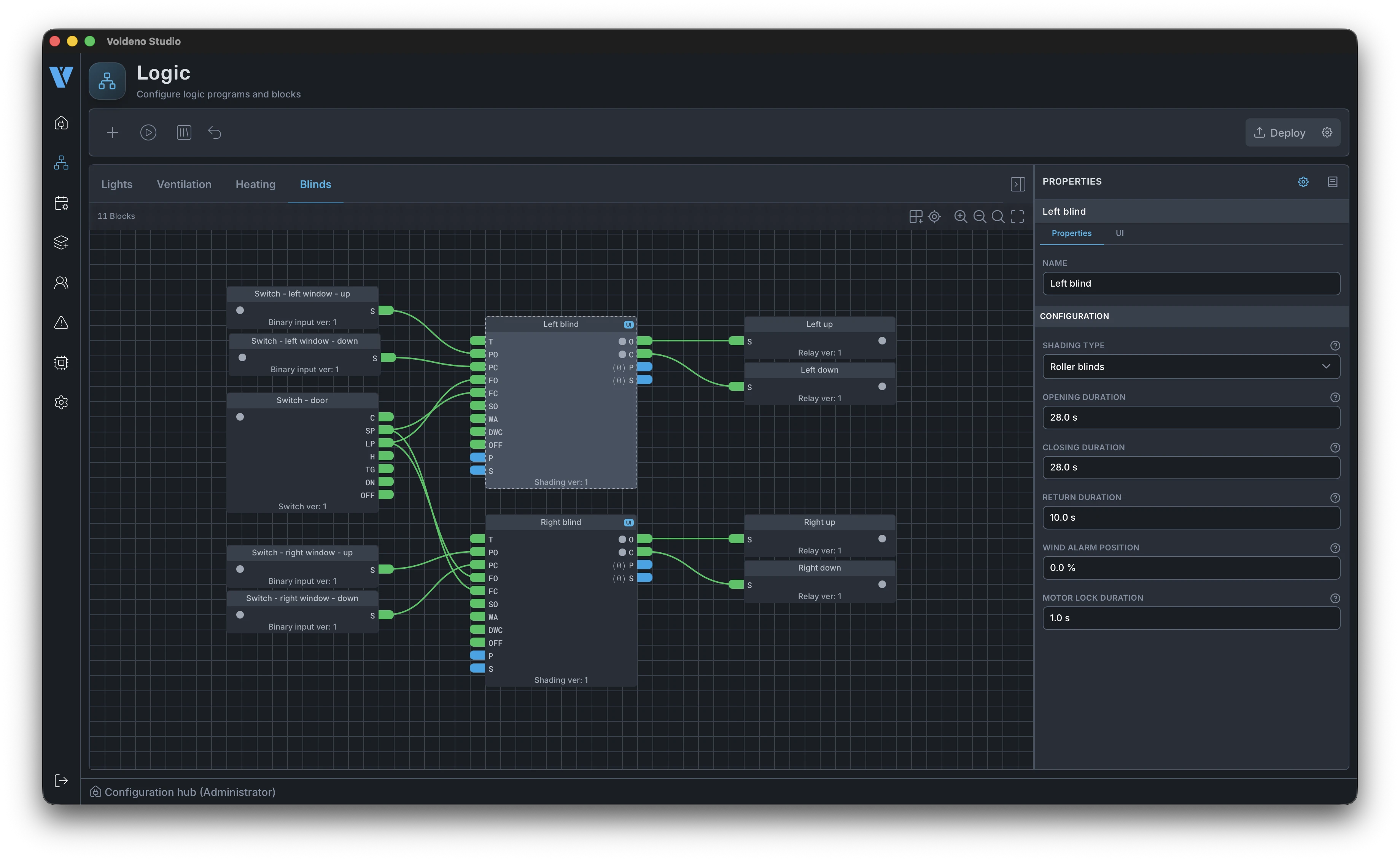
Drive block documentation is available the same way as for lighting — from the block properties on the canvas.
Before deploy you can simulate input and output changes in Studio. The simulation icon runs a test mode on the canvas: you set register values manually and watch how logic responds before it reaches the Hub. That is especially useful for blind sequences, schedules, and multi-input conditions.
# Deploy logic to the Hub
When the project in all groups is ready and simulation matches expectations, click Deploy in the top-right corner of Studio.
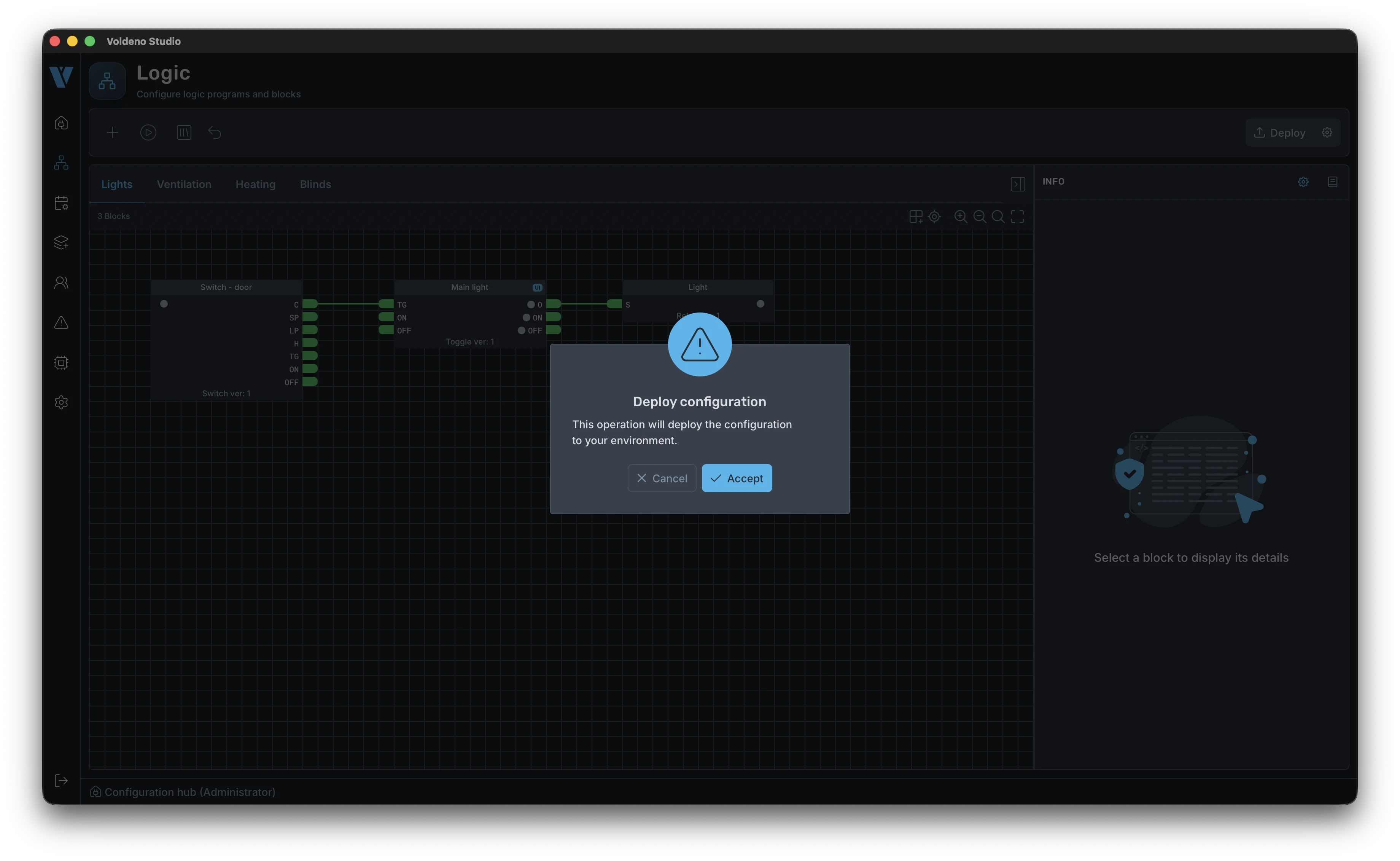
Deployment syncs the full configuration to the Hub instance: groups, blocks, connections, and compiled Volang programs. Progress appears on a bar — when it finishes, logic runs locally on the Hub and bus modules, independent of whether Studio stays connected.
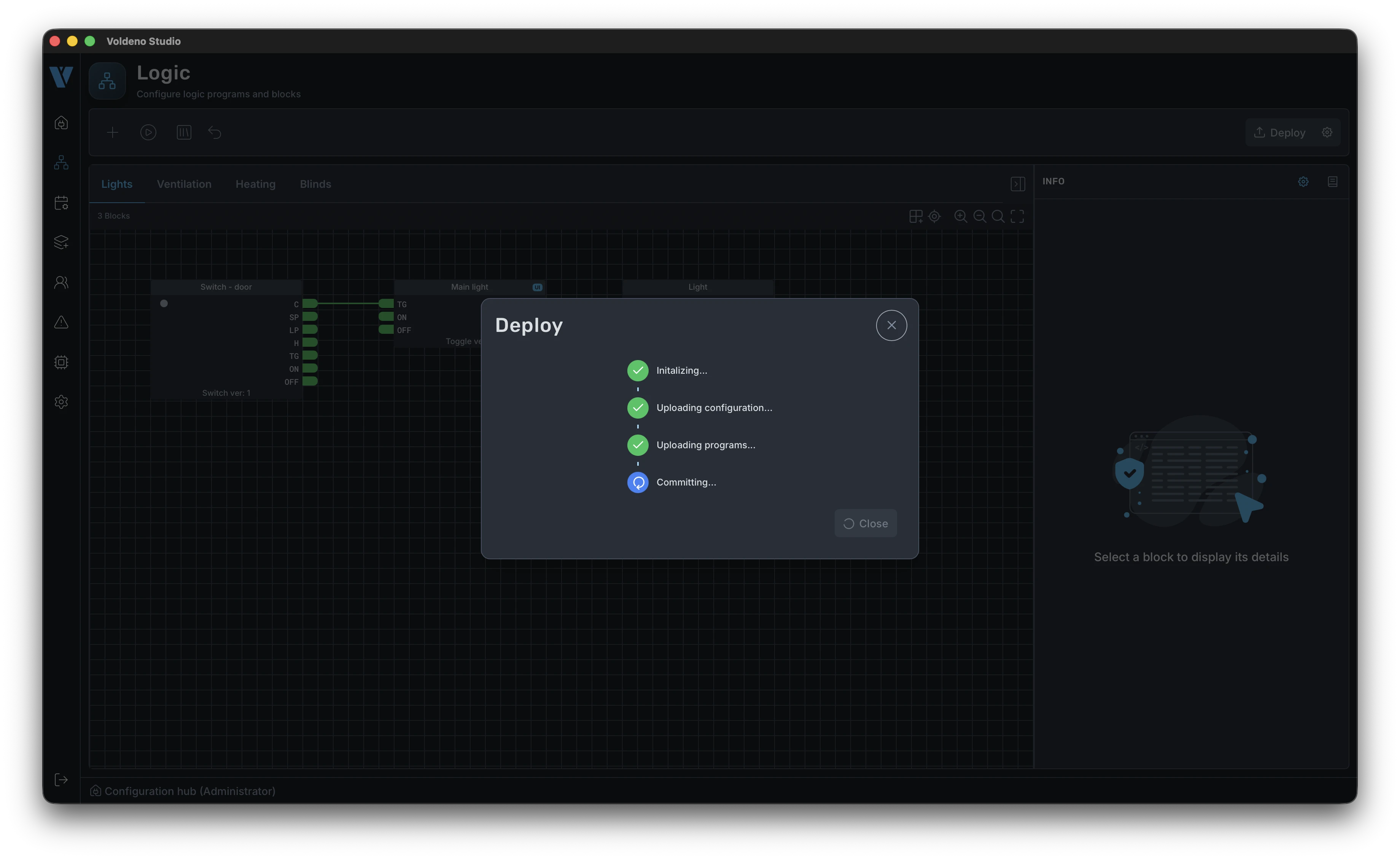
After deployment the Studio canvas shows the live state of the system: register values and block states reflect what is happening in the distribution board in real time.
# End-user access through Voldeno Mobile
Day-to-day control happens in Voldeno Mobile. To let a user connect a phone to the Hub securely, you define an account in Studio and generate a pairing token.
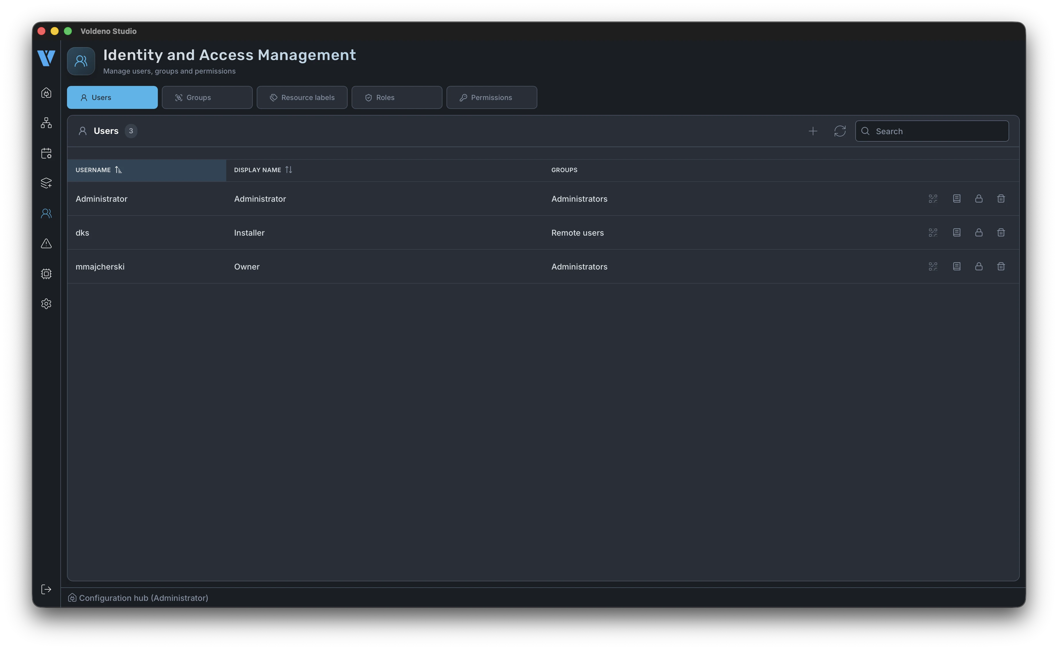
- Go to Users.
- Create a user with permissions that match their role (e.g. full home control, selected zones only).
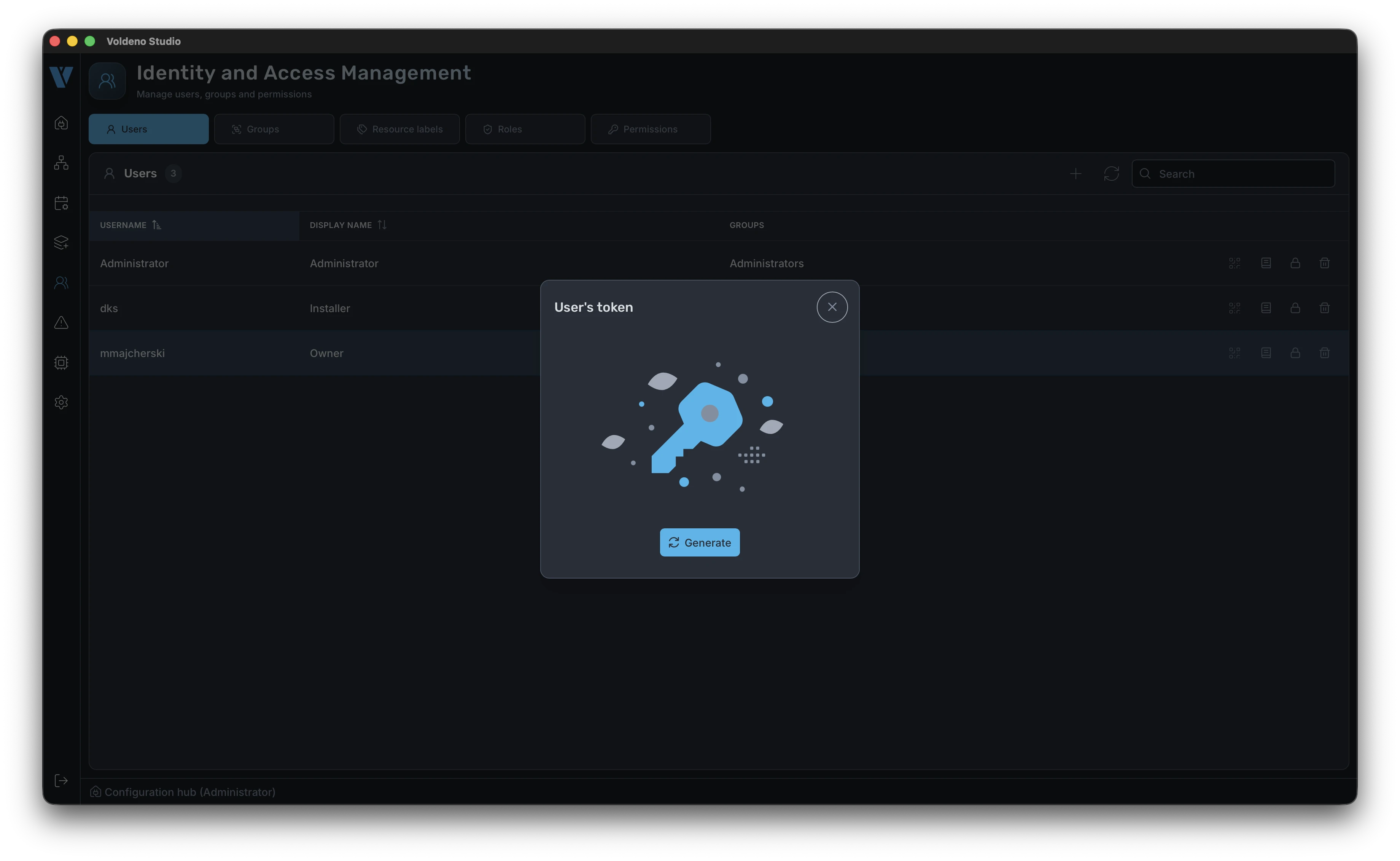
- Generate a pairing token for that user.
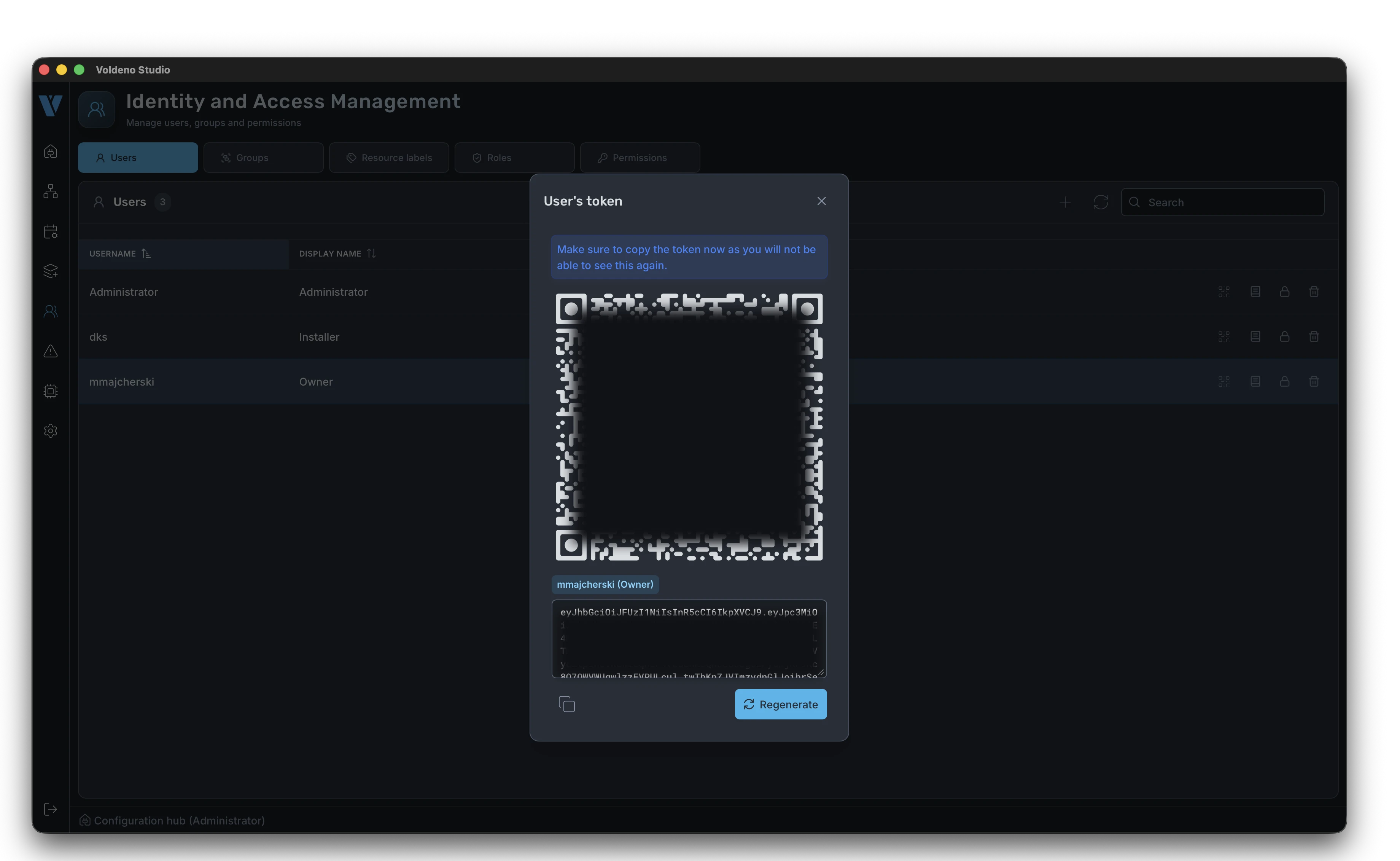
Studio displays the token with a QR code. The token is one-time and time-limited — save it or scan it in the app right away.
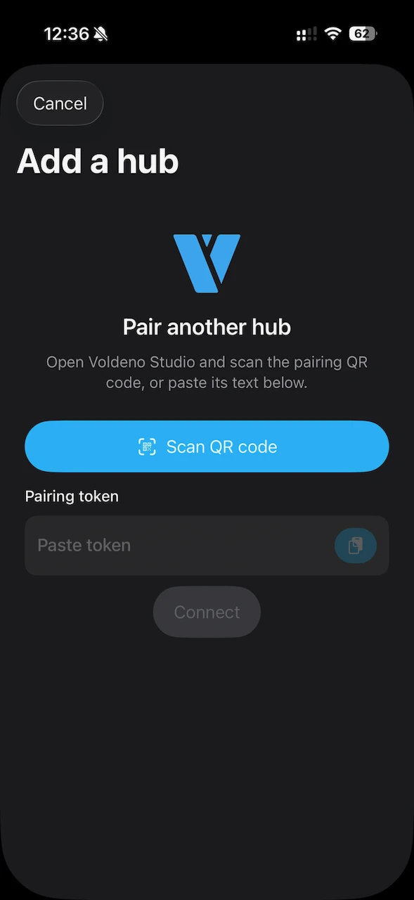
On the phone, open Voldeno Mobile, choose Hub pairing, and scan the QR code. The app establishes an encrypted connection to the installation — see Voldeno system security for the architecture.
# Control in the mobile app
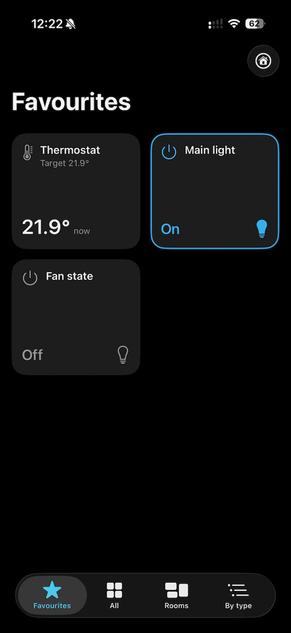
After pairing, all control tiles defined in logic are available in Mobile. The app groups them by type (lighting, blinds, heating, etc.) — layout follows block names and types from your Studio project.
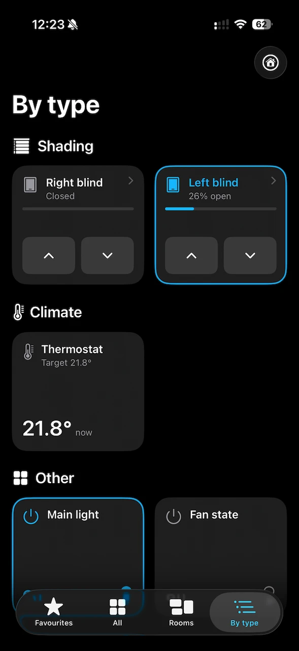
The user can add frequently used functions to favourites and operate them in one tap, e.g. an evening scene or a lighting zone.
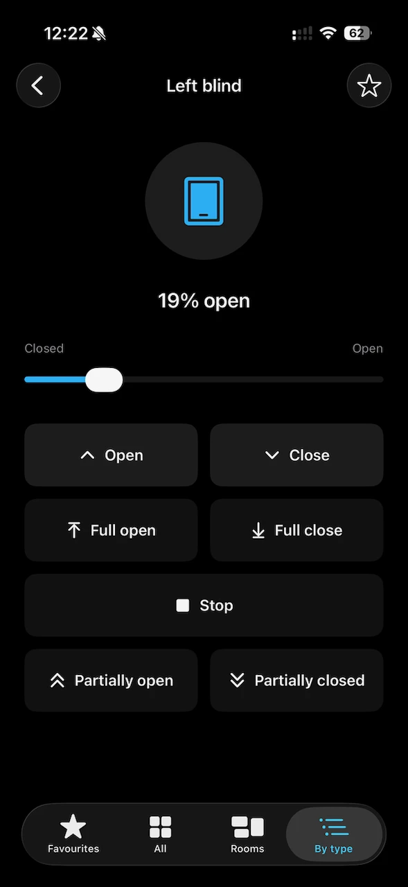
A detailed view of a single device (here: a blind) shows current state and available actions — the same registers and blocks you configured in Studio.
# What's next
| Topic | Article |
|---|---|
| Studio install and overview | Voldeno Studio |
| Logic block catalog | Logic blocks overview |
| Custom logic in Volang | Volang and VolangVM |
| Bus topology | Bus topology and wiring |
| Security and encryption | System security |
After these steps you have the full loop: logic defined in Voldeno Studio, deployed locally on the Hub, and available to the user in Mobile — from mDNS Hub discovery through pairing token scan.