# 1-Wire Module Wiring
Run 1-Wire buses on signal cables, away from 230 V AC conductors. Avoid loops and stubs in bus topology. Installation must be carried out by a qualified electrician in accordance with local regulations.
This guide covers Voldeno 1-Wire module (1W-A-D-1) wiring: the terminal map, two independent W1 and W2 buses, powered and parasitic modes, and temperature sensor connections. Ratings and use cases are on the 1-Wire product page.
# Module overview
The 2-DIN 1-Wire module collects temperature readings from digital sensors in a Voldeno installation:
| Area | Channels | Summary |
|---|---|---|
| 1-Wire buses | 2 (W1, W2) | Independent data paths; up to 20 sensors per bus |
| Sensor supply | 5V + GND | 5 V output for powered mode (powered buses only) |
| Bus | 1 × Voldeno Bus | 24 V DC module supply, GND, CAN-FD (BUS+, BUS−) |
The module supports up to 40 sensors total (DS18B20 and compatible). Built-in diagnostics detect shorts on each bus. Set sensor addresses and labels in Voldeno Studio.
# Terminal map
1-Wire bus terminals are on the top edge of the module; the Voldeno Bus connector is on the bottom.
# Top row: 1-Wire buses
| Terminal | Function |
|---|---|
| 5V | Sensor supply in powered mode (5 V DC) |
| GND | Common ground for buses and sensors |
| W1 | Data line for bus 1 |
| W2 | Data line for bus 2 |
# Bottom row: Voldeno Bus
| Terminal | Function |
|---|---|
| 24V | Module supply from the bus |
| GND | Bus ground |
| BUS+ | CAN High |
| BUS− | CAN Low |
Voldeno Bus topology is described in Bus topology and wiring.
# Connecting sensors
The diagram below shows four sensors on two buses: W1 in powered mode and W2 in parasitic mode. Labels #1, #20, #21, and #40 show the numbering ranges: bus W1 covers sensors #1–#20, bus W2 covers #21–#40 (up to 20 sensors per bus, 40 total per module).
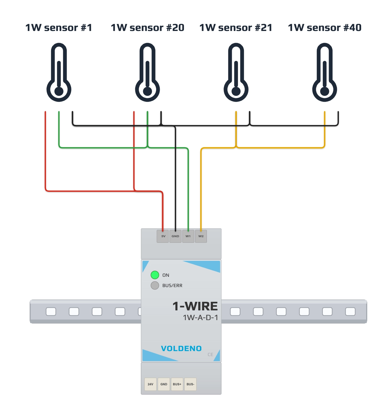
| Example on diagram | Bus | Mode | Wiring |
|---|---|---|---|
| Sensor #1 | W1 | Powered | 3 wires: 5V, W1, GND |
| Sensor #20 | W1 | Powered | Same mode as all other sensors on W1 |
| Sensor #21 | W2 | Parasitic | 2 wires: W2, GND (no 5V) |
| Sensor #40 | W2 | Parasitic | Same mode as all other sensors on W2 |
# Powered mode (bus W1 on the diagram)
Use on the entire W1 bus (or on the entire W2 bus if you choose powered mode on the second path):
- Connect module 5V to the sensor supply wire on that bus.
- Connect W1 (or W2) to the 1-Wire data line.
- Connect module GND to the shared sensor ground.
- Wire each sensor in parallel along the bus (linear topology or short branches per project limits).
5V comes from the 1-Wire module and is intended only for sensors on a bus configured in powered mode.
# Parasitic mode (bus W2 on the diagram)
Use on the entire W2 bus (or on the entire W1 bus if you choose parasitic mode on the first path):
- Connect the data line to W2 (or W1).
- Connect sensor ground to module GND.
- Do not connect 5V to sensors on this bus. The sensor draws power from the data line.
# One bus, one mode
Each bus (W1 or W2) runs entirely in powered mode or entirely in parasitic mode. Do not mix modes on the same bus: if one sensor on W1 uses 5V, every sensor on W1 must use 5V; if W2 is parasitic, no sensor on W2 gets separate 5V.
You may configure the two buses differently: e.g. W1 powered and W2 parasitic, as in the diagram.
# Installation sequence
- Mount the module on the DIN rail. Power the Voldeno Bus according to bus topology.
- Connect 24V, GND, BUS+, and BUS− to the adjacent module or bus segment.
- Confirm in Voldeno Studio that module 1W-A-D-1 appears in the device list.
- Plan sensor split across W1 and W2 and choose powered or parasitic mode separately for each bus.
- Run 1-Wire cabling. Connect sensors in parallel to W1 or W2 and GND; use 5V only on a bus in powered mode.
- In Studio, discover sensors, assign addresses and labels (e.g. room, manifold, buffer tank).
- Verify readings and bus diagnostics (including short-circuit detection).
# Questions and answers
How many sensors can I connect to one bus?
Up to 20 sensors on W1 or on W2. The module supports up to 40 sensors across both buses.
Can I mix one powered and one parasitic sensor on W1?
No. The entire W1 bus (or entire W2 bus) must use one mode: either all sensors with 5V, or all parasitic.
When should I choose powered vs parasitic mode?
Powered mode with 5V gives more stable supply on longer buses and with more sensors. Parasitic mode simplifies wiring (2 wires) when bus length and sensor count allow it.
Which sensors are supported?
DS18B20 and compatible 1-Wire temperature sensors. Confirm compatibility in the module documentation and sensor datasheet.
What does short-circuit detection do?
The module detects a short on bus W1 or W2 and reports the fault in Studio, which helps locate a damaged cable run.
# Next steps
- 1-Wire module — specifications and use cases
- Analog Input module wiring — 0-10 V and 4-20 mA sensors
- Define logic in Voldeno Studio
- Bus topology and wiring