# Analog Input Module Wiring
Run analog signal cables away from 230 V AC power conductors. Terminate cable shields per the sensor datasheet and your panel earthing concept. Installation must be carried out by a qualified electrician in accordance with local regulations.
This guide covers Voldeno Analog Input module (AIN-A-D-1) wiring: the terminal map, connecting four 0-10 V voltage inputs, four 0/4-20 mA current inputs, and the Voldeno Bus connector. Ratings and use cases are on the Analog Input product page.
# Module overview
The 2-DIN Analog Input module brings classic transducer signals into a Voldeno installation:
| Area | Channels | Range |
|---|---|---|
| Voltage inputs | 4 (V1–V4) | 0-10 V |
| Current inputs | 4 (C1–C4) | 0/4-20 mA |
| Bus | 1 × Voldeno Bus | 24 V DC supply, GND, CAN-FD (BUS+, BUS−) |
The module provides 8 independent analog inputs in total. Scale and filter each channel separately in Voldeno Studio (units, thresholds, charts). Typical uses include pressure, humidity, CO₂, level, and temperature probes, plus auxiliary signals from boilers, pumps, and air-handling units.
# Terminal map
Input terminals are on the top edge of the module; the bus connector is on the bottom.
# Top block: analog inputs
| Terminal | Input type |
|---|---|
| V1, V2, V3, V4 | Voltage 0-10 V |
| C1, C2, C3, C4 | Current 0/4-20 mA |
The upper row carries V1–V4; the row below carries C1–C4 on the AIN-A-D-1 module.
# Bottom row: Voldeno Bus
| Terminal | Function |
|---|---|
| 24V | Module supply from the bus |
| GND | Module ground and common signal reference |
| BUS+ | CAN High |
| BUS− | CAN Low |
GND on the bus connector is the shared reference for connected sensors (signal return). Bus topology is described in Bus topology and wiring.
# Connecting sensors
The module accepts typical HVAC and building-automation transducer outputs. The diagram below shows four example signal types, sensor power from the panel, and the shared GND reference.
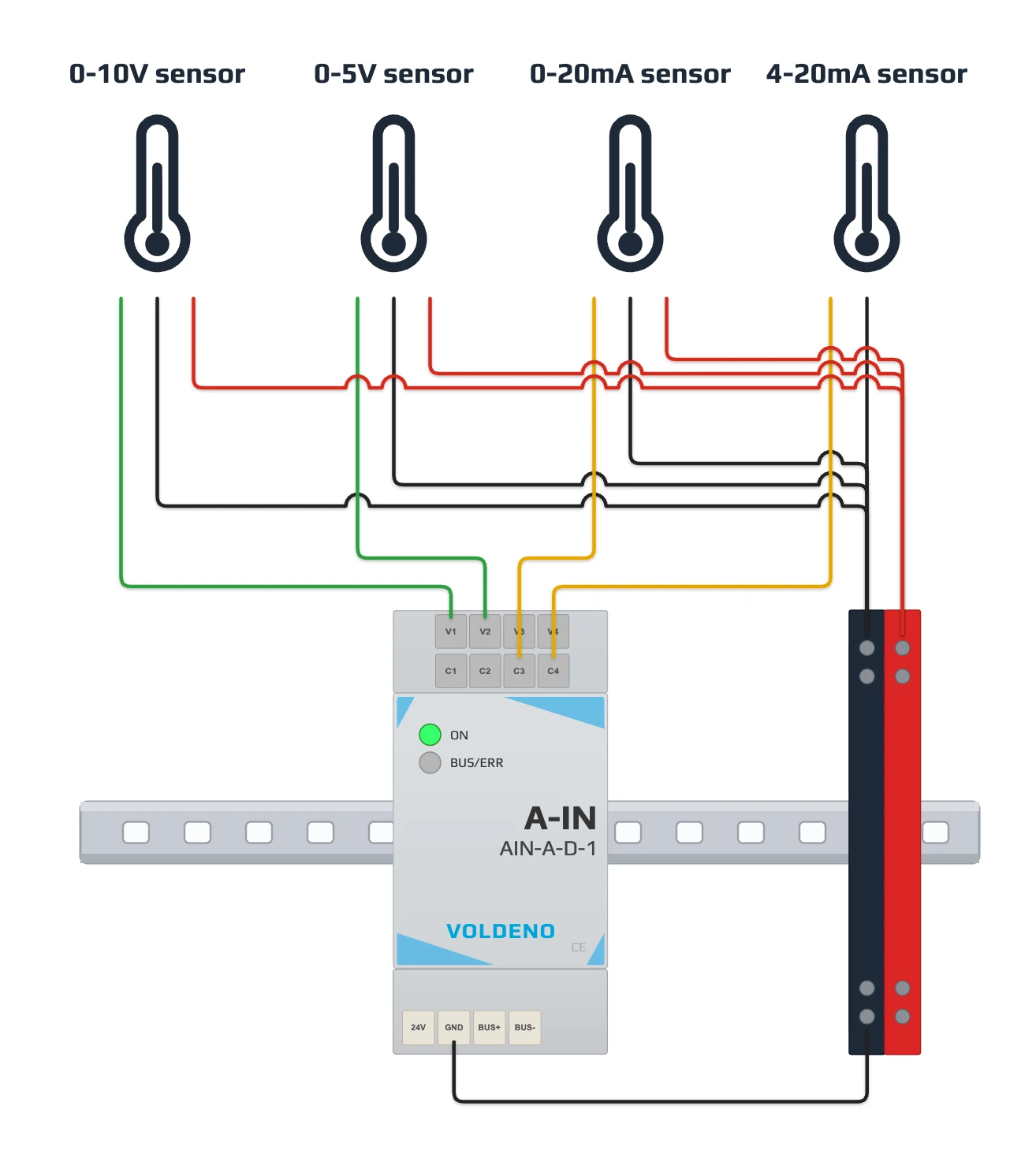
| Example on diagram | Terminal | Notes |
|---|---|---|
| 0-10 V sensor | V1 | Full voltage input range; 3-wire power |
| 0-5 V sensor | V2 | Fits a 0-10 V channel; set scaling in Studio |
| 0-20 mA loop | C3 | Current input; 3-wire layout with separate supply on the diagram |
| 4-20 mA loop | C4 | 2-wire loop; no separate sensor supply |
# Sensor power supply
The Analog Input module does not power sensors from Vx, Cx, or the Voldeno Bus (except GND as the signal reference). The diagram shows power from a separate source in the panel (+V block and GND bus).
- Choose supply voltage and power only per the sensor datasheet (e.g. 24 V DC, 12 V DC). The level must match that sensor model, not the AIN module.
- 3- or 4-wire sensors (typical 0-10 V, 0-5 V, some 0-20 mA layouts): connect separate +V and GND from an auxiliary supply, as in the diagram. Tie the supply ground to module GND.
- 2-wire 4-20 mA loops (active transmitter): energy comes from the loop itself. Do not add a separate supply unless the manufacturer requires it (as in the 4-20 mA example on the diagram).
- Select and protect the sensor supply independently of the Voldeno module. Do not exceed rated voltage on Vx inputs and do not feed loops from Cx terminals.
# Voltage inputs (V1–V4)
- Connect the sensor signal output (e.g. 0-10 V or 0-5 V) to V1, V2, V3, or V4.
- Connect the sensor signal ground to module GND (common reference, as in the diagram).
- Power the sensor from an external source per its datasheet (3- or 4-wire layout). Set supply voltage per the manufacturer specification.
- In Voldeno Studio, set input type, source range (e.g. 0-5 V on a 0-10 V channel), and target unit.
Do not exceed 10 V on Vx terminals. For non-standard ranges, use an external signal converter.
# Current inputs (C1–C4)
- Connect the sensor current loop output (0-20 mA or 4-20 mA) to C1, C2, C3, or C4.
- Connect the other loop pole (return or ground) to module GND when the sensor layout requires it.
- 2-wire loop (4-20 mA): the loop itself provides power; no separate +V to the sensor is needed. 3-wire loop (e.g. 0-20 mA): add supply per the datasheet, as in the diagram.
- In Studio, select loop type (0-20 mA or 4-20 mA) and scaling to the physical quantity.
The module measures current in the input path. Do not power loops or sensors from the Analog Input Cx terminals.
# Installation sequence
- Mount the module on the DIN rail. Power the Voldeno Bus according to bus topology.
- Connect 24V, GND, BUS+, and BUS− to the adjacent module or bus segment.
- Confirm in Voldeno Studio that module AIN-A-D-1 appears in the device list.
- Route analog signal cables separately from power wiring. Wire sensor supplies (where required), signals to V1–V4 or C1–C4, and GND.
- In Studio, configure each channel: signal type, scaling, filter, and units.
- Compare module readings with a reference (multimeter, transducer display) and adjust coefficients.
# Questions and answers
Can I connect a 0-5 V sensor to a 0-10 V input?
Yes. Use a Vx terminal and set a 0-5 V input range plus scaling to the physical value (e.g. % RH, °C) in Studio.
What is the difference between 0-20 mA and 4-20 mA?
Both connect to C1–C4. Select the loop type in Studio. 4-20 mA allows broken-loop detection (signal below 4 mA).
Do all sensors need a common GND?
Yes. Sensor signal returns should tie to module GND, as in the diagram, so voltage and current measurements share one reference.
When should I choose Analog Input instead of 1-Wire?
1-Wire supports up to 40 temperature sensors on a digital bus. Analog Input is the right choice when you already have a 0-10 V or 4-20 mA transducer (HVAC, BMS, plant room) and want to integrate it into Voldeno logic without rewiring.
Does the module power the sensors?
No. When sensors need a supply, feed it from a separate source in the panel, with voltage and power per the sensor datasheet. The exception is 2-wire 4-20 mA loops, where the loop itself provides power.
Do analog inputs work with the I/O module?
Yes. Analog Input readings can drive the same logic as digital inputs and relay outputs from I/O and RELAY in Voldeno Studio.
# Next steps
- Analog Input module — specifications and use cases
- I/O module wiring — digital inputs and relay outputs
- 1-Wire module wiring — temperature sensors on 1-Wire
- Define logic in Voldeno Studio
- Bus topology and wiring