# I/O Module Wiring
Work on I/O module terminals involves field circuits at 230 V AC or 24 V DC. De-energize field wiring before connecting conductors. Installation must be carried out by a qualified electrician in accordance with local regulations.
This guide covers Voldeno I/O module (IO-A-D-1) wiring: the terminal map, connecting eight 24 V DC digital inputs, eight relay outputs in two isolated groups, and the Voldeno Bus connector. Electrical ratings and use cases are on the I/O product page.
# Module overview
The 4-DIN I/O module connects the Voldeno installation to field circuits:
| Area | Channels | Summary |
|---|---|---|
| Digital inputs | 8 (I1–I8) | Wall switches, dry contacts, pulse counters (up to 250 Hz) |
| Relay outputs | 8 (O1–O8) | NO contacts in 2 groups of 4, 230 V AC or 24 V DC |
| Bus | 1 × Voldeno Bus | 24 V DC supply, GND, CAN-FD (BUS+, BUS−) |
Each group of four relays has its own load supply terminals (L/N) and its own current measurement. The groups are fully isolated: you can wire independent circuits or different voltage levels within the rated limits.
# Terminal map
Terminals are on the top edge of the module (inputs and outputs) and on the bottom (bus).
# Top row: relay outputs
| Group | Supply terminals | NO outputs |
|---|---|---|
| Group 1 | N1, L1 | O1, O2, O3, O4 |
| Group 2 | N2, L2 | O5, O6, O7, O8 |
L1 / L2 are the common phase (or DC positive) for four relays in the group. N1 / N2 are the common neutral (or DC negative) for loads in the group. Each Ox output switches an NO contact between Lx and Ox.
# Second row: digital inputs
| Bank | Auxiliary supply | Inputs |
|---|---|---|
| Bank 1 | 24V | I1, I2, I3, I4 |
| Bank 2 | 24V | I5, I6, I7, I8 |
The 24V terminals provide the 24 V DC reference for connected push buttons and dry contacts. Do not power loads from them: they are for input sensing only.
# Bottom row: Voldeno Bus
| Terminal | Function |
|---|---|
| 24V | Module supply from the bus |
| GND | Bus ground |
| BUS+ | CAN High |
| BUS− | CAN Low |
Bus topology, termination, and length limits are described in Bus topology and wiring.
# Connecting digital inputs
I/O inputs are voltage-activated at 24 V DC. A typical circuit is a push button or dry contact closing the loop between the bank 24V terminal and the selected Ix input.
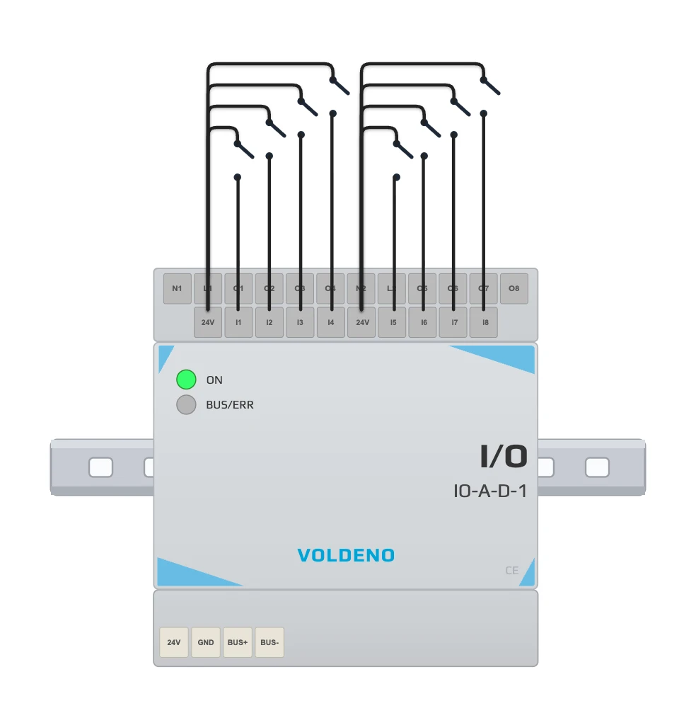
Steps:
- Connect one side of the button (or the common wire for a bank of contacts) to the 24V terminal of the bank that serves that input (bank 1 for I1–I4, bank 2 for I5–I8).
- Connect the other side of each button to the matching I1–I8 terminal.
- In Voldeno Studio, assign each input to logic (button, door/window contact, pulse counter, and so on).
Typical input uses:
- Wall switches and local push buttons
- Window and door contacts
- PIR motion sensor outputs (dry contact)
- S0 energy meters, flow meters, and other pulse sources (frequency counter mode up to 250 Hz)
# Connecting relay outputs
Outputs are NO (normally open) contacts. The relay closes the path between Lx and Ox when the channel is turned on in logic.
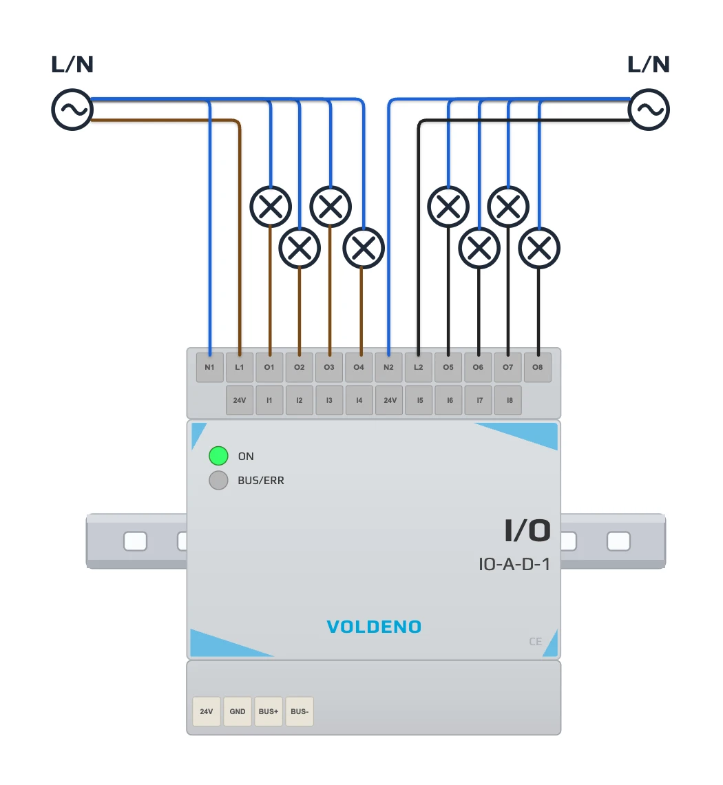
AC example (group 1, lighting):
- Connect L1 to the circuit phase and N1 to the neutral of the same circuit.
- Run the shared neutral to one side of each load in the group.
- Connect the other side of each load to O1, O2, O3, or O4 according to the channel mapped in Studio.
Group 2 (O5–O8) works the same way through L2, N2, and outputs O5–O8. You can feed the second group from a different panel circuit as long as you respect isolation and current limits.
# Current limits
The same limit applies to each relay and to the whole group of four outputs:
| Load category | Max current | Voltage |
|---|---|---|
| AC1 (resistive, cos φ = 1) | 5 A | 250 V AC |
| AC15 (inductive, cos φ = 0.4) | 2 A | 250 V AC |
| DC1 (resistive) | 5 A | 30 V DC |
| DC13 (inductive, L/R = 7 ms) | 2 A | 30 V DC |
Minimum switching power: 0.05 W (10 mA at 5 V DC). For inductive loads (solenoid valves, coils) and LED drivers with high inrush current, use an external relay on a DIN rail socket or the RELAY module for higher switching currents.
# Current measurement and zero-crossing switching
The module measures current separately for each group of four relays (two sensors per module). Values are available in Voldeno Studio and Mobile after channels are configured.
For AC loads, relay channels use software zero-crossing switching: the module tracks the mains sine wave and closes contacts near 0 V. Technical background is in Zero-crossing switching on I/O and RELAY modules.
# Installation sequence
- Mount the module on the DIN rail in the panel. Power the Voldeno Bus according to bus topology.
- Connect 24V, GND, BUS+, and BUS− to the adjacent module or bus segment.
- Confirm in Voldeno Studio that module IO-A-D-1 appears in the device list.
- With field circuits de-energized, wire inputs (buttons, contacts).
- Wire loads on relay outputs, keeping the L1/N1 and L2/N2 group split.
- In Studio, map each input and output channel to registers that match the actual wiring.
- Test every channel: output switching, input reading, and group current measurement.
# Questions and answers
Do inputs need pull-up resistors?
No. The module provides 24 V DC on each bank 24V terminal. Closing the circuit between 24V and Ix with a button or contact is enough.
Can I mix 230 V AC and 24 V DC on one module?
Yes, within group isolation. Group 1 and group 2 are separated. Within a group, all four relays share Lx/Nx and the group current limit.
Why does the 5 A limit apply to the whole group of four outputs?
The current sensor and group supply paths are shared. The sum of simultaneously active loads in a group must not exceed 5 A (AC1/DC1) or 2 A (AC15/DC13).
When should I choose RELAY instead of I/O?
RELAY is intended for higher currents: electric heating, high-power LED drivers, blinds, and socket circuits. I/O suits lighting sections, valves, gates, and similar low to medium-power loads.
Can I use an input as a pulse counter?
Yes. Set frequency counter mode in Studio (up to 250 Hz) and wire the pulse source between 24V and Ix.
# Next steps
- I/O module — specifications and use cases
- Relay module wiring — higher switching currents
- Define logic in Voldeno Studio — map channels to logic blocks
- Bus topology and wiring