
What an I/O module is in a smart home and what it is for: inputs, outputs, how to size it. An installation example, a comparison table and FAQ.
# I/O module in a smart home: what it is and what it is for
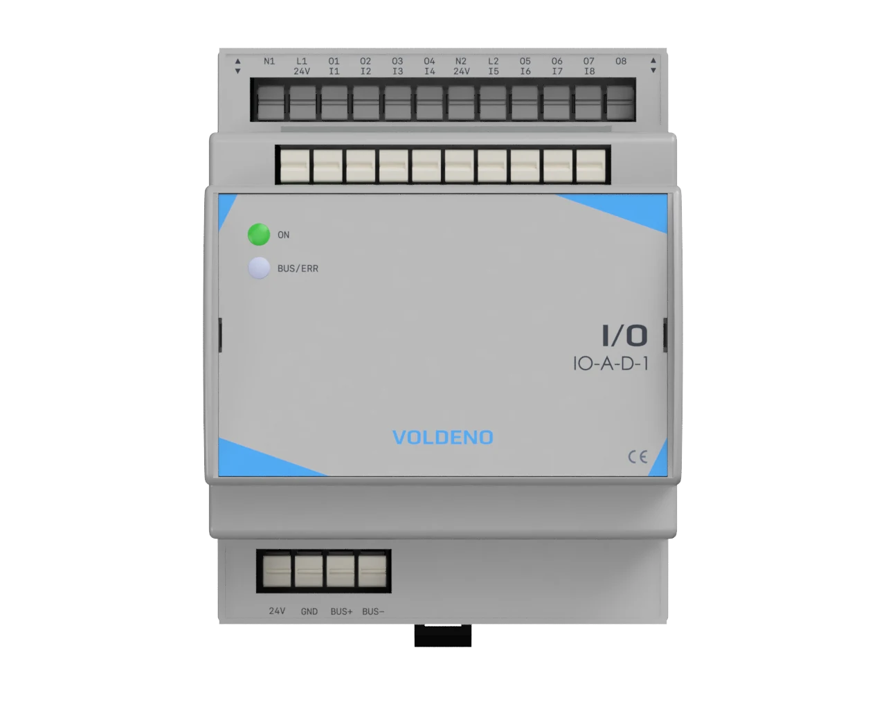
In the evening, after you get home, you press the button in the hallway. A 24 V DC signal runs through the wall to the distribution board and lands on a terminal of a module on the DIN rail. The module reports the press on the bus, the system logic decides what to do, and a relay on the output turns the lamp on. The whole path takes a fraction of a second and stays invisible to the user. That is how a well designed system should behave.
In brief: an I/O module (input/output) is a device in the distribution board that reads signals from buttons and sensors on its inputs and switches loads through its outputs. It does not decide on its own: it passes input states to the system logic and carries out that logic's commands. In a smart home it is the point where the wires from buttons and lamps meet the automation.
# What is an I/O module?
An I/O module translates the physical world into logic states and back. An input turns a closed button contact into the information "pressed". An output turns the command "on" into a closed relay contact that feeds voltage to a load.
A simple comparison is the human body. Inputs act as senses: they detect a button press, an open window or water in the laundry. Outputs act as hands that switch things on and off. The brain is the logic you configure in Voldeno Studio. In a Voldeno system that logic runs locally, on the Hub and on the modules on the bus, not on an external server.
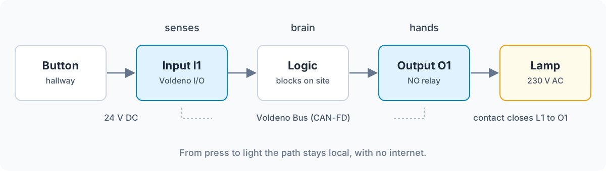
Datasheets often use the label 8DI/8DO. DI is digital input and DO is digital output. The Voldeno I/O module has that layout: eight 24 V DC digital inputs and eight relay outputs. "Digital" here means two states: voltage is present or it is not. For variable values, for example 0-10 V sensors, there is a separate Analog Input module.
The I/O abbreviation comes from computing, where it describes data exchange between a processor and external devices. Building automation kept the same term because the principle is the same.
# Digital inputs: what can you connect?
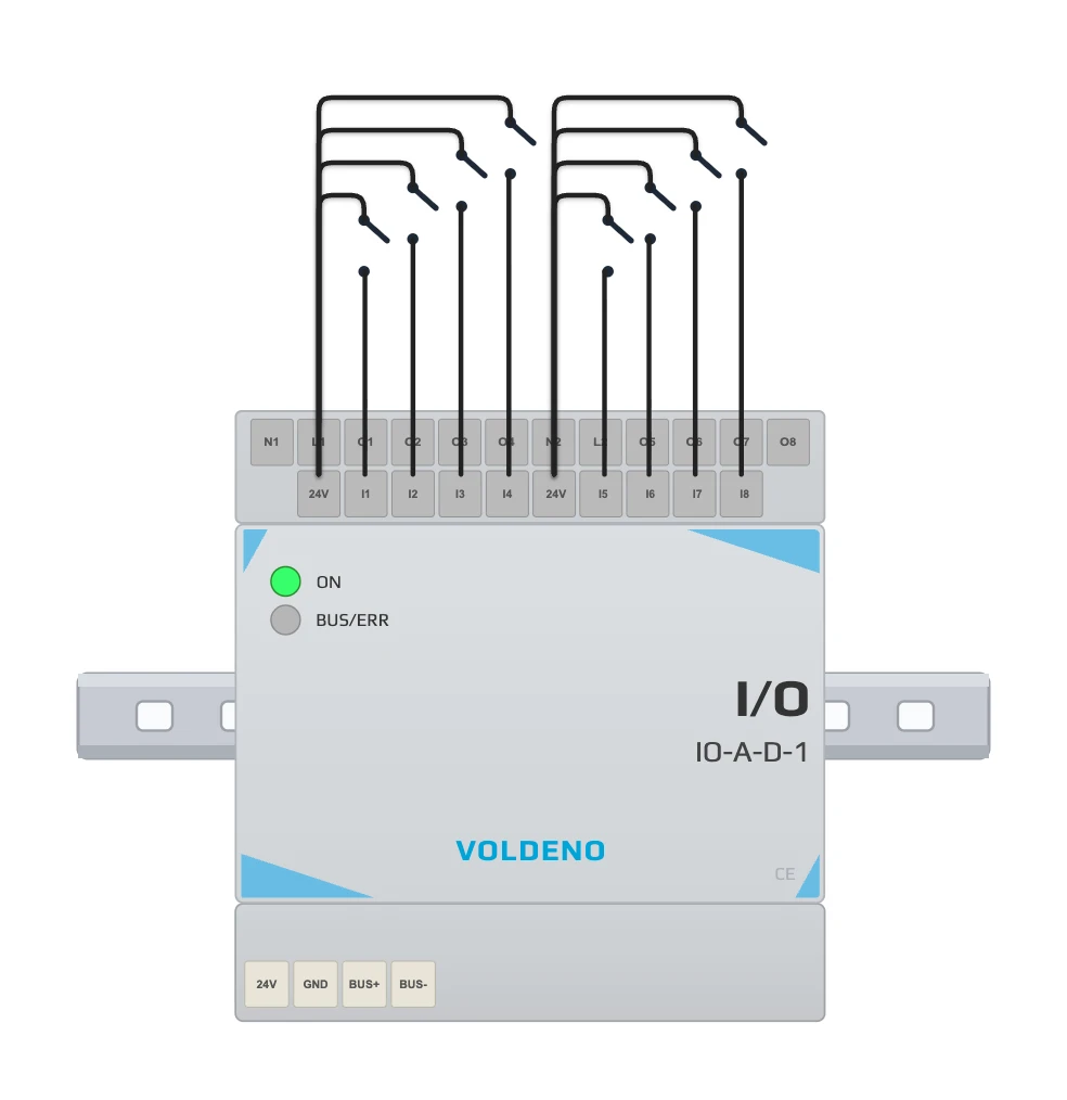
A digital input accepts anything that closes or opens a circuit: a button, a potential-free sensor contact or a pulse output from a meter. On the Voldeno I/O module the contact closes the loop between that bank's 24V terminal and the input (I1-I8), so pull-up resistors are not required.
| Device | What it signals | Home example |
|---|---|---|
| Wall button (momentary) | a press and how long it lasts | hallway light, "Leaving" scene at the door |
| Motion sensor | presence in a zone (potential-free contact) | night stair lighting |
| Window or door reed contact | open / closed | heating off when a window is open |
| Flood sensor | water on the floor | closing the main water valve in the plant room |
| Water or gas meter with a pulse output | successive volumes | daily water use in the app |
| Energy meter with an S0 output | successive energy increments | heat-pump consumption |
| Alarm panel signal | armed, alarm, tamper | scenes that depend on whether the house is armed |
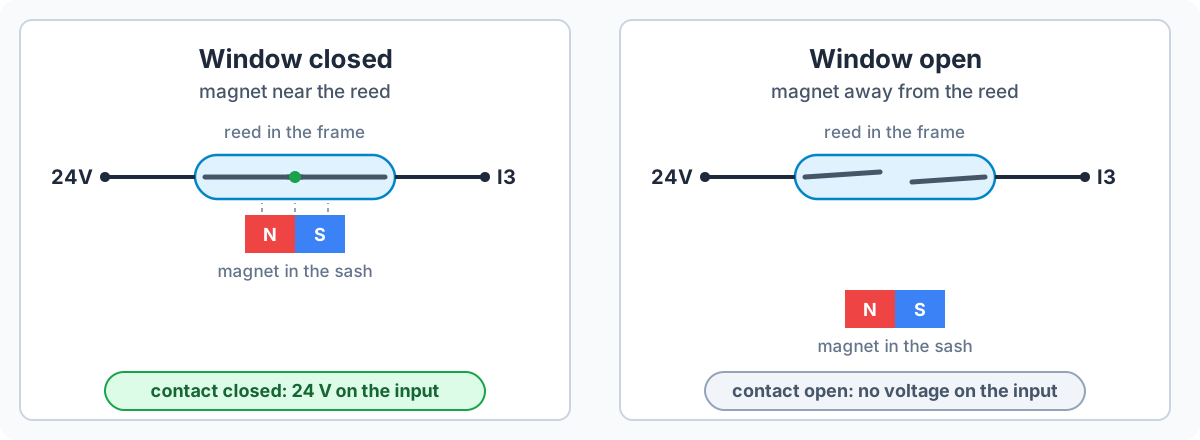
A reed contact is simple: two spring blades of ferromagnetic metal sealed in a glass tube. The magnet in the window sash pulls them together and closes the contact. When you open the window the magnet moves away and the blades separate.
Pulse meters work on a similar idea. Inside a water meter a magnet turns, and a reed or inductive pickup on the meter generates one pulse per revolution, that is per a fixed volume of water (1 or 10 litres, depending on the model). Voldeno I/O module inputs have a frequency-counter mode up to 250 Hz, which is also enough for energy meters with an S0 output.
# Why buttons, not ordinary switches?
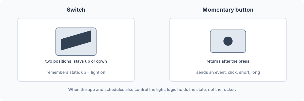
An ordinary switch has two stable positions and "remembers" state: up means the light is on. In a house that is also controlled from an app and from schedules, the rocker soon no longer matches the real lighting state. A momentary button (like a doorbell) returns to its rest position and only sends an event. The logic decides whether the light is on.
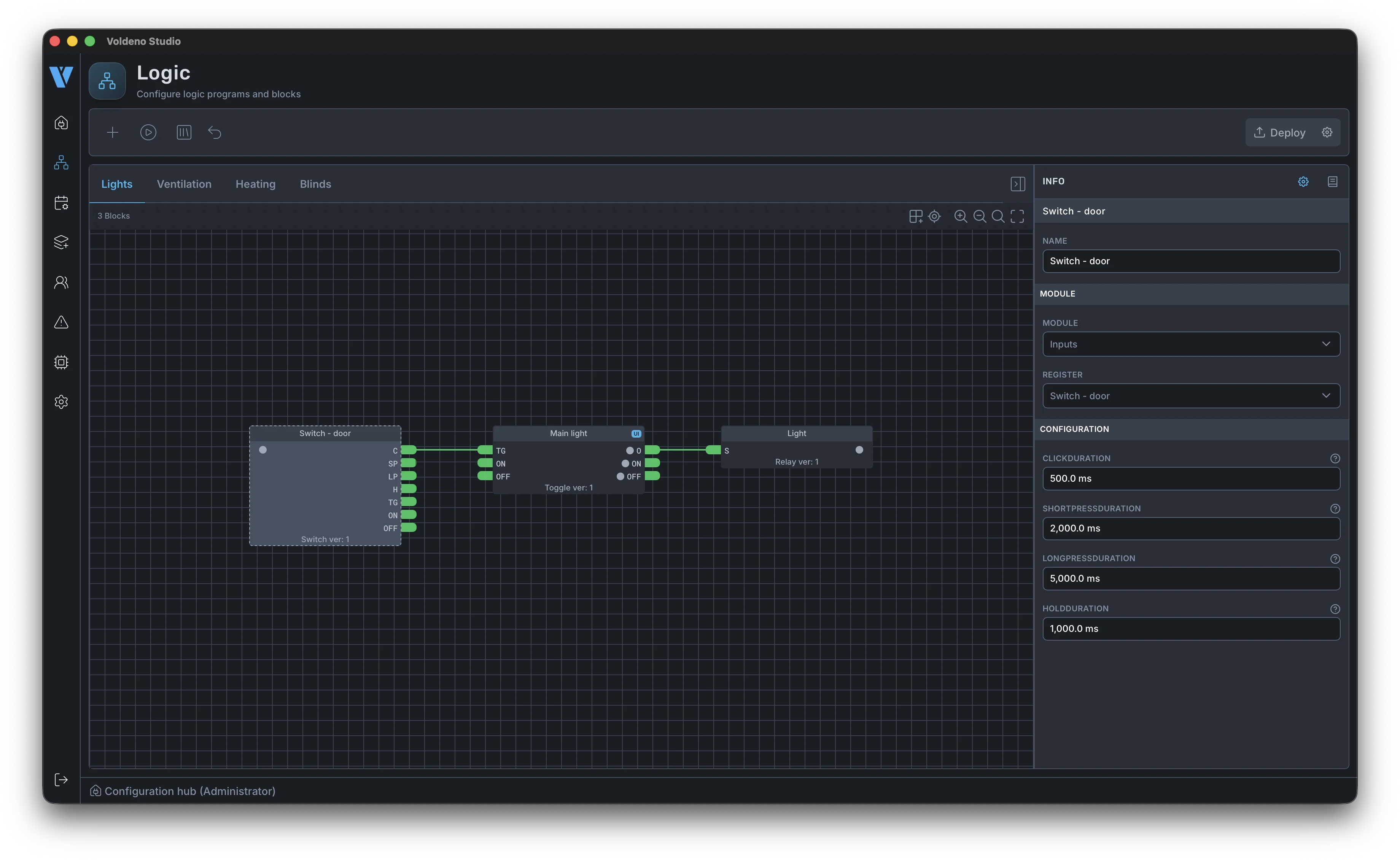
A button can also do more than one job. The switch block in Voldeno Studio distinguishes a click, a short press, a long press and a hold, with thresholds set in milliseconds. The same key at the door can turn on the hallway light on a short press and turn off the lights in the whole house on a longer hold.
# Relay outputs: what you switch and where the limits are
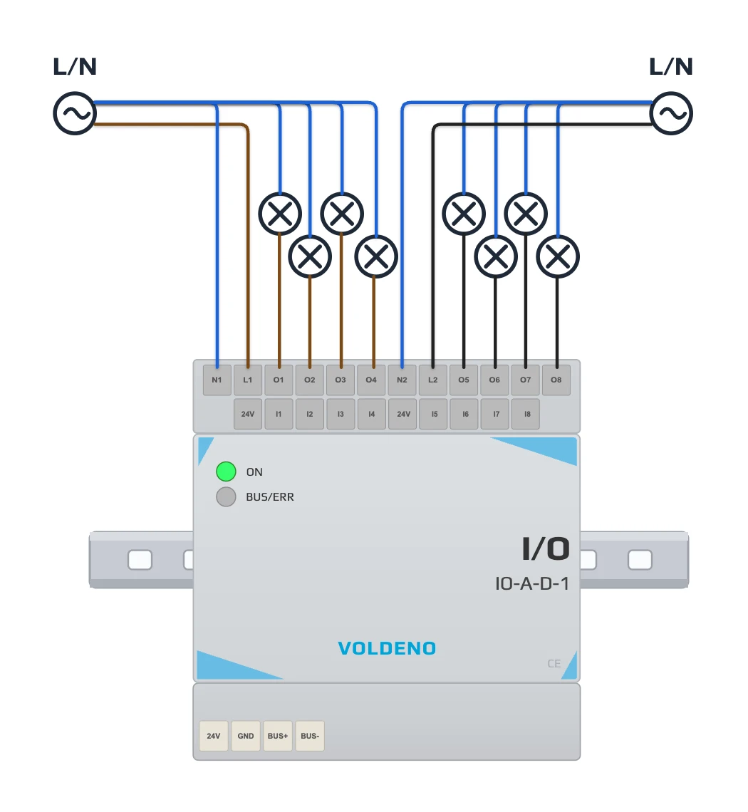
A relay output is an NO (normally open) contact that closes on a logic command and feeds voltage to a load. The Voldeno I/O module has eight such outputs in two isolated groups of four. Each switches up to 5 A at 250 V AC (resistive load, category AC1).
Typical uses:
- lighting sections: hallway ceiling, wall lights, facade lighting;
- a pulse for a gate controller or a gate strike;
- solenoid valves, for irrigation or a water shut-off valve;
- a bathroom fan and similar small motors.
The 5 A limit applies to a single channel and to the sum of the whole group of four outputs. For inductive loads such as valve coils or fans the limit is 2 A (category AC15). The groups are fully isolated, so one can be fed from a 230 V AC lighting circuit and the other from 24 V DC for a gate and valves.
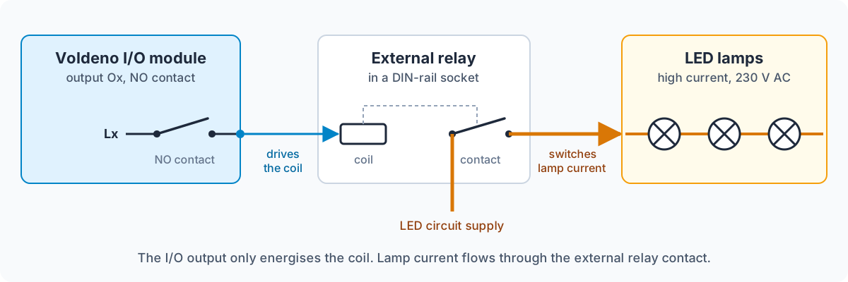
The I/O module is not meant for electric heating, socket circuits, blinds or high-power LED drivers. Those loads belong on the RELAY module, with four outputs up to 16 A per channel in category AC1. A second option is external DIN-rail relays driven from I/O outputs: the output energises the coil, and the relay switches the high current. That works when you need higher switching current and do not need per-circuit current measurement (see the real installation below).
Every AC output on the I/O module closes when mains voltage crosses zero, which limits inrush current and arcing on the contacts. Details are in the post on zero-crossing switching in the I/O and RELAY modules. On a 50 Hz supply the voltage crosses zero a hundred times a second, so the delay from synchronisation is not noticeable at the button.
# What does group current measurement give you?
The Voldeno I/O module has two current sensors, one per group of four relays. It measures the sum of current through the four outputs in the group, not each output on its own. The reading is available in Voldeno Studio and in the Voldeno Mobile app.
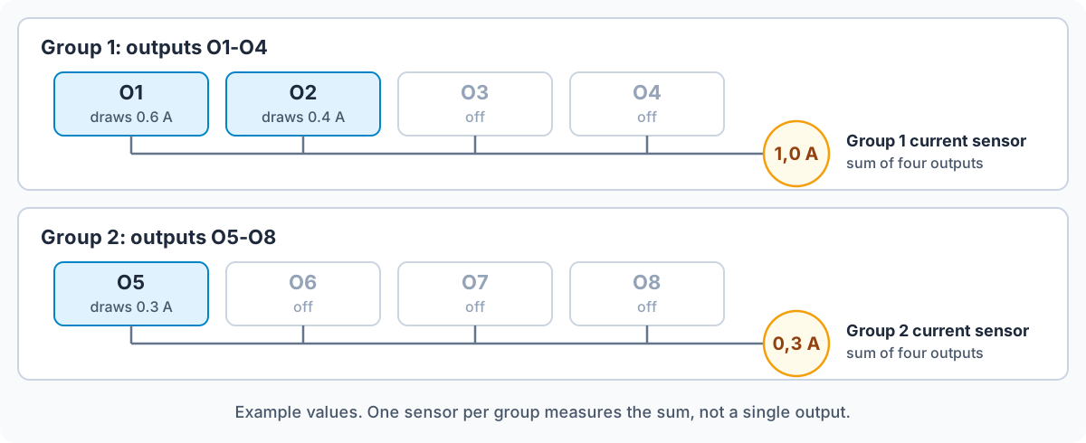
That reading shows how close the group is to the 5 A limit when all of its circuits are on. If only one circuit in the group is on, the reading is that circuit's current. If the group current does not rise after a channel is turned on, the load is drawing no energy: a failed lamp or an open circuit. When you need a measurement on every circuit, for example to account for heater use, choose the RELAY module, which has a current sensor on each channel.
# How the I/O module works with the rest of the system
The I/O module needs a Hub in the same installation and talks to it over the Voldeno Bus. It mounts in the distribution board on a 35 mm DIN rail, next to the protective devices, not in the wall box behind the button.
The Voldeno Bus is four wires: 24 V DC supply, ground and two CAN-FD data lines. It is daisy-chained from module to module through the connector on each one, without extra bus-power modules. CAN was developed at Bosch in the 1980s for communication between vehicle controllers, where the link has to tolerate electrical noise and vibration. CAN-FD is a later version with higher throughput.
Roles in the system are split. The Hub joins the installation to Ethernet, stores data and handles remote access. In Voldeno Studio you map each input and output to logic blocks. Voldeno Mobile is for day-to-day control and monitoring.
What happens if the internet fails or is missing? Buttons, sensors and scenes keep working, because the logic runs locally in the installation. You only lose remote access from outside the home network. A Hub failure also does not automatically shut down the whole automation, because the modules and distributed logic still work over the bus (more in the system overview).
# I/O modules at home and in industry: what is different?
The electrical principle is the same. The workplace and the required skill are not. In industrial automation, I/O modules are usually part of a PLC system programmed in IEC 61131-3 languages such as ladder (LD) or structured text (ST). That needs specialist programming knowledge and the PLC vendor's tools.
The Voldeno I/O module does the same electrical job, but you configure it in Voldeno Studio with ready-made logic blocks, without writing code. For more complex cases the Volang language is available.
| PLC with I/O modules | Wired smart home (e.g. Voldeno) | Relays and controllers wired by hand | Wireless in-box devices | |
|---|---|---|---|---|
| Voltages | inputs usually 24 V DC, transistor or relay outputs | 24 V DC inputs, relay outputs 230 V AC or 24 V DC | usually 230 V AC on buttons and relay coils | 230 V AC in the box, radio control |
| Programming | IEC 61131-3 in the PLC vendor's environment, needs programming skill | configuration in Studio with logic blocks, code optional | none, the function is defined by how the wires are connected | vendor app, often with a cloud account |
| Who installs it | automation engineer or integrator | electrician after system training | electrician | electrician or the homeowner |
| Reliability | designed for years of continuous duty | wired, local logic, no Wi-Fi dependency | simple and durable, but no information about circuit state | depends on radio range, batteries and the router |
| Cost of expansion | another module plus programming work | another module on the bus and a change in Studio | new cables and hardware for every change of function | cheap per point, but grows with every box |
A PLC is the right tool in industrial automation, where cycle time is deterministic and a specialist team runs the plant. A home system should be simple to start and unlimited in configuration: typical scenes are built without code, and complex ones can grow in Volang. The high entry barrier of PLC programming is a drawback in a house, not a feature. Changing a lighting scene should not require a specialist with a laptop.
# Example from a real installation: what the I/O module does when there are many lamps
The photo is a section of the distribution board in one of our installations. On the right, an I/O module and a RELAY module sit side by side. On the left are orange relays in DIN-rail sockets.
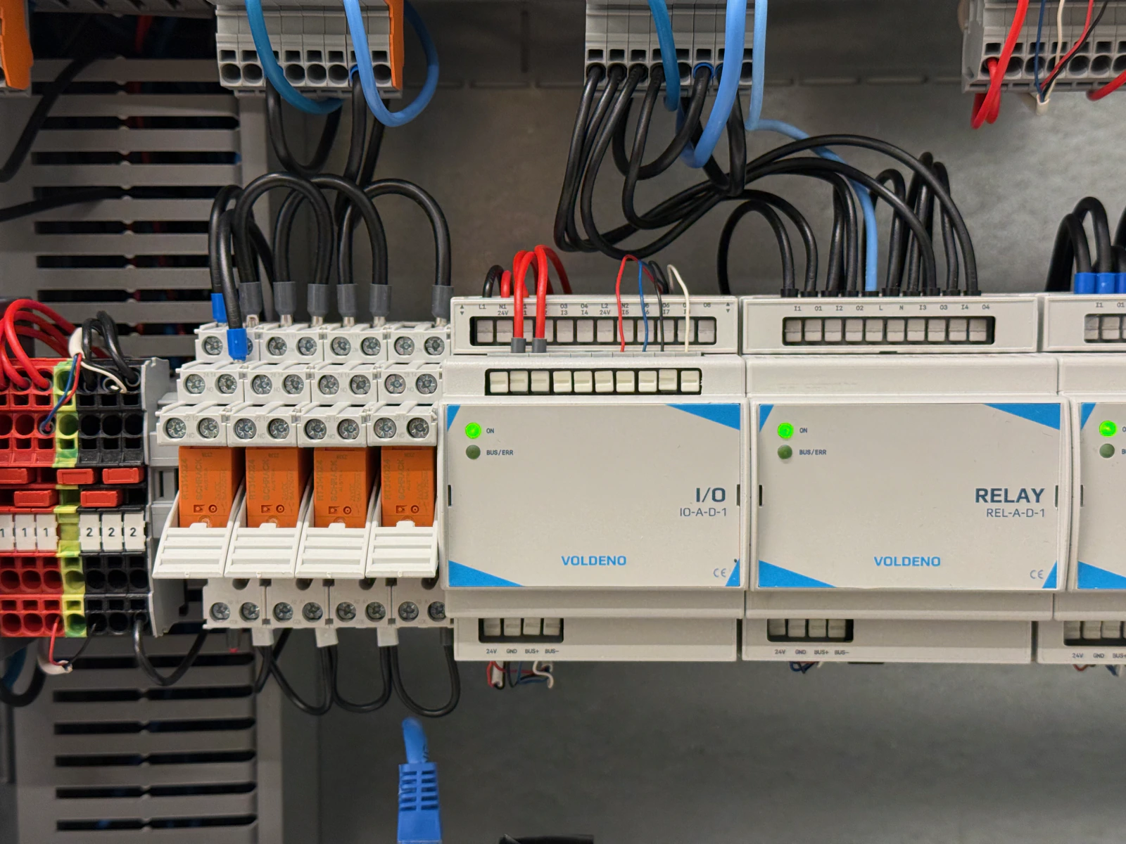
Back to the hallway button. In this installation its signal lands on an I/O input, because the module is used mainly as an input bank. Wall-switch cables terminate on its terminals, including the ones that control the blinds.
The lighting is a large number of powerful LED lamps whose current exceeds the I/O module's 5 A limit. External relays (orange in the photo) switch them, and their coils are driven from I/O outputs. The RELAY module drives the blinds.
| Part of the installation | Connected to | Role |
|---|---|---|
| Lighting wall switches | I/O module inputs | events for the logic: short and long press |
| Blind wall switches | I/O module inputs | up and down commands for the logic |
| LED lamps | external relays driven from I/O outputs | high-current switching |
| Blind motors | RELAY module outputs | motor supply |
This is an alternative to adding more RELAY modules when you need higher switching current and circuit current measurement is not critical. There is a trade-off: extra hardware appears in the board, and the I/O current sensor then measures the relay coils, not the lamp current. When you need the circuit current, RELAY is the better choice.
# How many I/O modules does a house need?
Count low-power inputs and outputs separately, divide each number by eight and take the larger result. Loads above the I/O module limits (heating, sockets, blinds) should be counted as RELAY modules or as external relays driven from I/O outputs. Add reserve for later expansion: the guide on smart home design mistakes recommends 30-50%.
Inputs usually run out first. Every button, reed contact and sensor takes one, and a house with sensors on every window can have a dozen reed contacts alone. Lighting outputs are usually fewer, because one circuit feeds several luminaires.
For scale: the Modern barn project runs seven I/O modules, nine RELAY modules, one Analog Input module and two 1-Wire modules, with one Hub. Full hardware and cost breakdowns for an apartment, a 120 m² house and a house above 200 m² are in how much a smart home costs.
# FAQ
# How does a PLC differ from an I/O module?
A PLC is a controller that runs a program. An I/O module is its inputs and outputs, the connection to sensors and loads. In a Voldeno system the controller role is the logic that runs locally on the Hub and the modules. The I/O module supplies the signals and carries out the commands.
# What does 8DI/8DO mean?
Eight digital inputs and eight digital outputs. The Voldeno I/O module has that layout: eight 24 V DC inputs and eight relay outputs in two groups of four.
# Can I wire an ordinary wall switch instead of a button?
Yes. The input will read its position, and in Studio you can react to every change of state. You lose the distinction between a short and a long press, and the rocker no longer matches the light when the light is also controlled from the app. That is why we recommend momentary buttons in new installations.
# Is 5 A on an output enough for LED lighting?
For typical circuits, yes: 5 A at 230 V is about 1150 W of resistive load, and a room LED circuit is usually a few tens of watts. Remember that 5 A is also the sum limit for a group of four outputs. For many powerful LED lamps or drivers with a high inrush current, use a RELAY module or external relays driven from I/O outputs.
# Does the I/O module work without internet?
Yes. Buttons, sensors, scenes and schedules run locally in the installation. No internet only removes remote access from outside the house.
# I/O module or RELAY module?
The I/O module is for buttons, sensors and loads up to 5 A: lighting, gates, valves. RELAY has four outputs up to 16 A with current measurement on each channel and has no digital inputs, so it is for heating, sockets, blinds and motors. When you need higher current and do not need circuit current measurement, I/O outputs can also drive external relays. Most houses use both modules.
# Summary
The I/O module is an unobtrusive but most-used part of the installation. Every hallway button press, every window opening and every pulse from a water meter passes through its terminals, and its outputs turn lights on or drive relays without the user and without internet access. Sized with spare channels, and with heavy loads moved to RELAY modules or external relays, it needs no attention for years.
If you are planning an installation and want to check how many I/O modules your house needs, book a free consultation. We will match modules to your project. You can also download Voldeno Studio for free and configure inputs and outputs in simulation.